Основной каталог Kyocera 2016-2017 - страница 581
Навигация
 Каталог Kyocera фрезы MFH для высокоскоростной обработки
 Каталог Kyocera фрезы MEC высокопроизводительные концевые и торцевые фрезы
 Каталог микроинструмента Kyocera 2015-2016
 Каталог Kyocera высокоэффективные сверла со сменными пластинами DRV
 Каталог Kyocera пластины TQ для нарезания резьбы c прессованным стружколомом
 Каталог Kyocera высокопроизводительные модульные сверла DRA
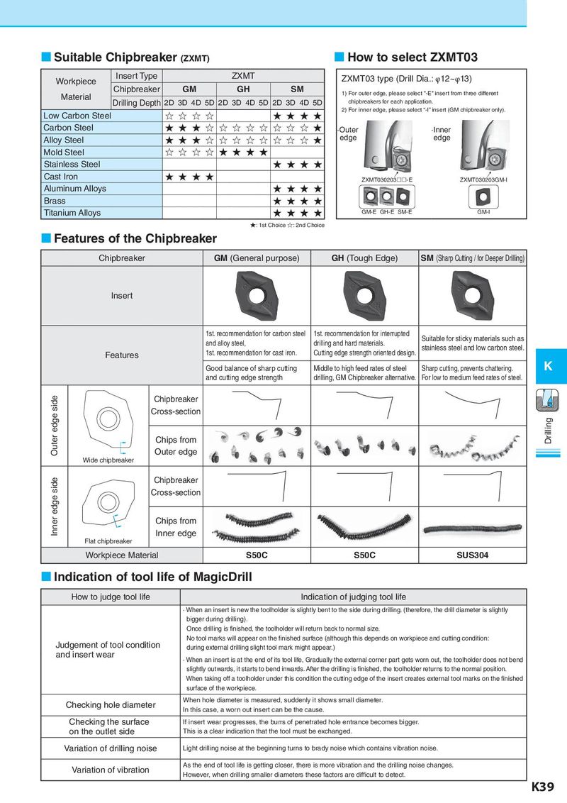
Suitable Chipbreaker (ZXMT) How to select ZXMT03 Workpiece Insert Type ZXMT ZXMT03 type (Drill Dia.: φ12~φ13) Chipbreaker GM GH SM 1) For outer edge, please select "-E" insert from three different Material Drilling Depth 2D 3D 4D 5D 2D 3D 4D 5D 2D 3D 4D 5D chipbreakers for each application. Low Carbon Steel ☆ ☆ ☆ ☆ ★ ★ ★ ★ 2) For inner edge, please select “-I” insert (GM chipbreaker only). Carbon Steel ★ ★ ★ ☆ ☆ ☆ ☆ ☆ ☆ ☆ ☆ ★ ·Outer ·Inner Alloy Steel ★ ★ ★ ☆ ☆ ☆ ☆ ☆ ☆ ☆ ☆ ★ edge edge Mold Steel ☆ ☆ ☆ ☆ ★ ★ ★ ★ Stainless Steel ★ ★ ★ ★ Cast Iron ★ ★ ★ ★ → → ZXMT030203-E ZXMT030203GM-I Aluminum Alloys ★ ★ ★ ★ Brass ★ ★ ★ ★ Titanium Alloys ★ ★ ★ ★ GM-E GH-E SM-E GM-I ★: 1st Choice ☆: 2nd Choice Features of the Chipbreaker Chipbreaker GM (General purpose) GH (Tough Edge) SM (Sharp Cutting / for Deeper Drilling) Insert 1st. recommendation for carbon steel 1st. recommendation for interrupted Suitable for sticky materials such as and alloy steel, drilling and hard materials. stainless steel and low carbon steel. Features 1st. recommendation for cast iron. Cutting edge strength oriented design. Good balance of sharp cutting Middle to high feed rates of steel Sharp cutting, prevents chattering. K and cutting edge strength drilling, GM Chipbreaker alternative. For low to medium feed rates of steel. Outer edge side Chipbreaker Cross-section Chips from Drilling Outer edge Wide chipbreaker Inner edge side Chipbreaker Cross-section Chips from Inner edge Flat chipbreaker Workpiece Material S50C S50C SUS304 Indication of tool life of MagicDrill How to judge tool life Indication of judging tool life · When an insert is new the toolholder is slightly bent to the side during drilling. (therefore, the drill diameter is slightly bigger during drilling). Once drilling is finished, the toolholder will return back to normal size. No tool marks will appear on the finished surface (although this depends on workpiece and cutting condition: Judgement of tool condition during external drilling slight tool mark might appear.) and insert wear · When an insert is at the end of its tool life, Gradually the external corner part gets worn out, the toolholder does not bend slightly outwards, it starts to bend inwards. After the drilling is finished, the toolholder returns to the normal position. When taking off a toolholder under this condition the cutting edge of the insert creates external tool marks on the finished surface of the workpiece. Checking hole diameter When hole diameter is measured, suddenly it shows small diameter. In this case, a worn out insert can be the cause. Checking the surface If insert wear progresses, the burrs of penetrated hole entrance becomes bigger. on the outlet side This is a clear indication that the tool must be exchanged. Variation of drilling noise Light drilling noise at the beginning turns to brady noise which contains vibration noise. Variation of vibration As the end of tool life is getting closer, there is more vibration and the drilling noise changes. However, when drilling smaller diameters these factors are difficult to detect. K39