Основной каталог Kyocera 2016-2017 - страница 567
Навигация
 Каталог Kyocera фрезы MFH для высокоскоростной обработки
 Каталог Kyocera фрезы MEC высокопроизводительные концевые и торцевые фрезы
 Каталог микроинструмента Kyocera 2015-2016
 Каталог Kyocera высокоэффективные сверла со сменными пластинами DRV
 Каталог Kyocera пластины TQ для нарезания резьбы c прессованным стружколомом
 Каталог Kyocera высокопроизводительные модульные сверла DRA
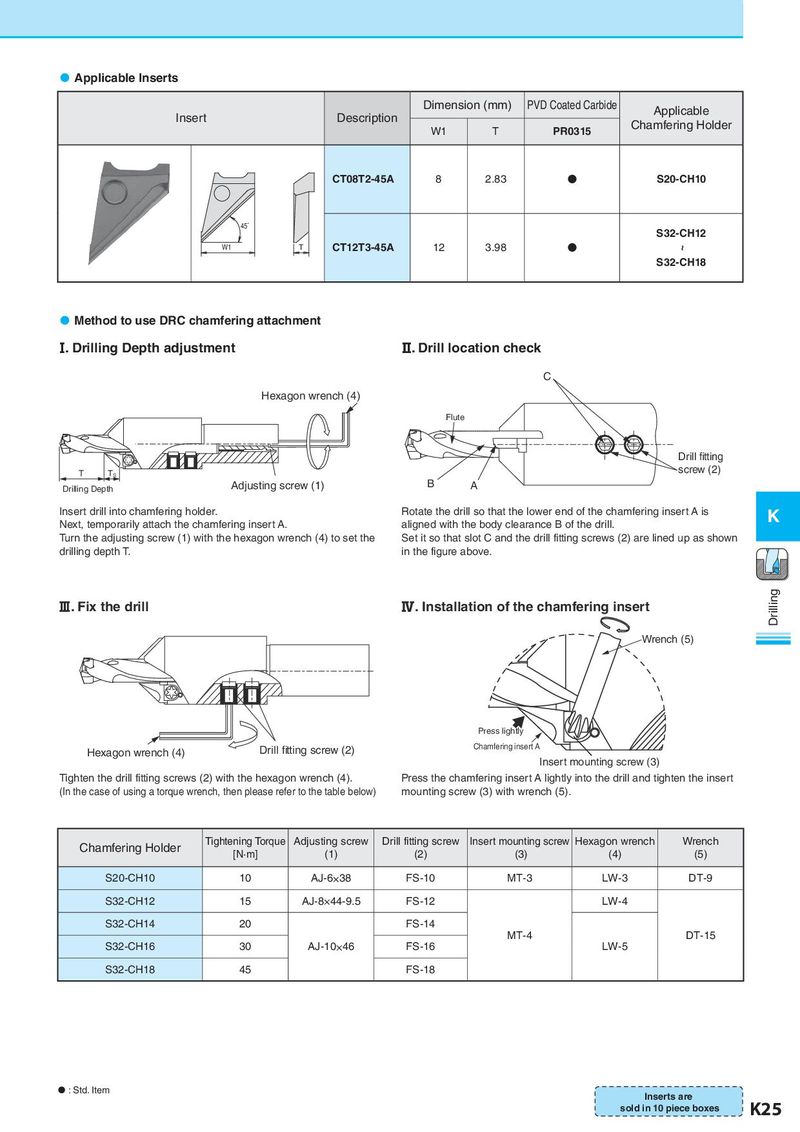
Applicable Inserts Dimension (mm) PVD Coated Carbide Applicable Insert Description Chamfering Holder W1 T PR0315 CT08T2-45A 8 2.83 N S20-CH10 45˚ S32-CH12 W1 T CT12T3-45A 12 3.98 N ~ S32-CH18 Method to use DRC chamfering attachment Ⅰ. Drilling Depth adjustment Ⅱ. Drill location check C Hexagon wrench (4) Flute Drill tting T TS screw (2) Drilling Depth Adjusting screw (1) B A Insert drill into chamfering holder. Rotate the drill so that the lower end of the chamfering insert A is K Next, temporarily attach the chamfering insert A. aligned with the body clearance B of the drill. Turn the adjusting screw (1) with the hexagon wrench (4) to set the Set it so that slot C and the drill fitting screws (2) are lined up as shown drilling depth T. in the figure above. Ⅲ. Fix the drill Ⅳ. Installation of the chamfering insert Drilling Wrench (5) Press lightly Hexagon wrench (4) Drill tting screw (2) Chamfering insert A Insert mounting screw (3) Tighten the drill fitting screws (2) with the hexagon wrench (4). Press the chamfering insert A lightly into the drill and tighten the insert (In the case of using a torque wrench, then please refer to the table below) mounting screw (3) with wrench (5). Chamfering Holder Tightening Torque Adjusting screw Drill fitting screw Insert mounting screw Hexagon wrench Wrench [N·m] (1) (2) (3) (4) (5) S20-CH10 10 AJ-6×38 FS-10 MT-3 LW-3 DT-9 S32-CH12 15 AJ-8×44-9.5 FS-12 LW-4 S32-CH14 20 FS-14 MT-4 DT-15 S32-CH16 30 AJ-10×46 FS-16 LW-5 S32-CH18 45 FS-18 : Std. Item Inserts are sold in 10 piece boxes K25