Основной каталог Kyocera 2016-2017 - страница 470
Навигация
 Каталог Kyocera фрезы MFH для высокоскоростной обработки
 Каталог Kyocera фрезы MEC высокопроизводительные концевые и торцевые фрезы
 Каталог микроинструмента Kyocera 2015-2016
 Каталог Kyocera высокоэффективные сверла со сменными пластинами DRV
 Каталог Kyocera пластины TQ для нарезания резьбы c прессованным стружколомом
 Каталог Kyocera высокопроизводительные модульные сверла DRA
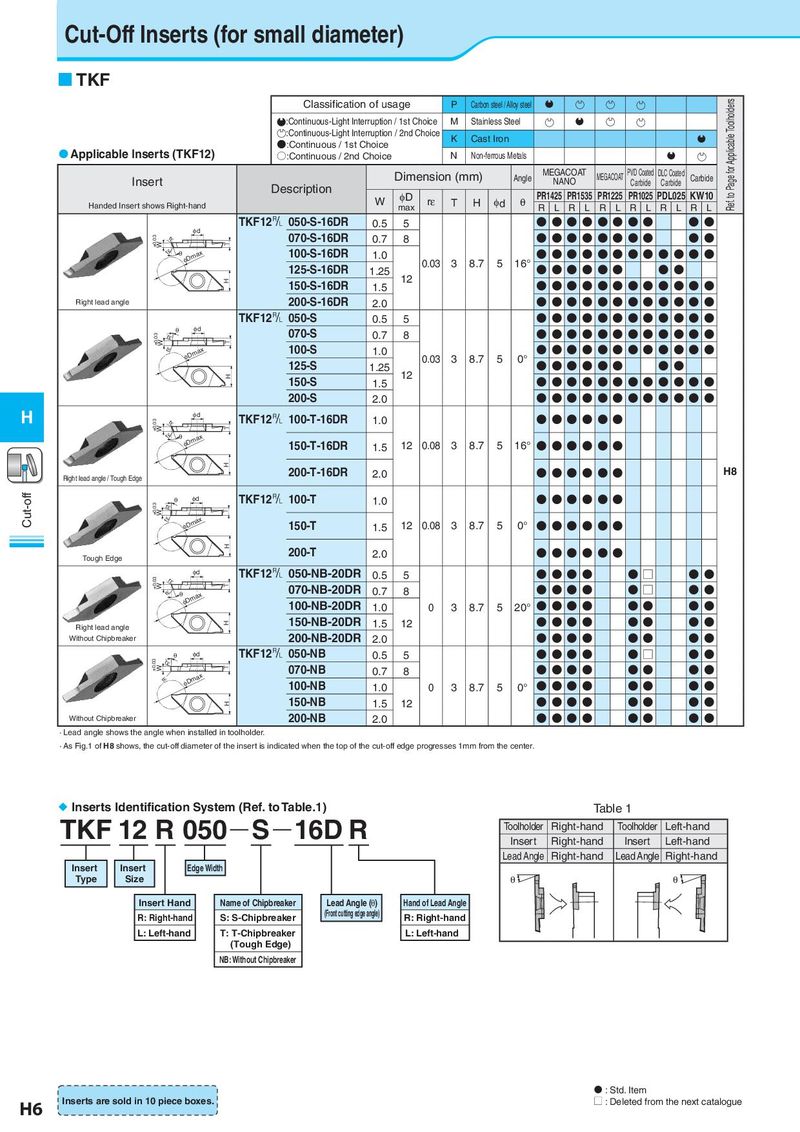
Cut-Off Inserts (for small diameter) TKF Classification of usage P Carbon steel / Alloy steel Q Ref. to Page for Applicable Toolholders :Continuous-Light Interruption / 1st Choice M Stainless Steel Q :Continuous-Light Interruption / 2nd Choice K Cast Iron Q Applicable Inserts (TKF12) ●:Continuous / 1st Choice ○:Continuous / 2nd Choice N Non-ferrous Metals Q Dimension (mm) Angle MEGACOAT MEGACOAT PVD Coated DLC Coated Carbide Insert Description NANO Carbide Carbide W φD rε T H φd θ PR1425 PR1535 PR1225 PR1025 PDL025 KW10 Handed Insert shows Right-hand max R L R L R L R L R L R L TKF12& 050-S-16DR 0.5 5 ●●●● ●● ●● ●● φd 070-S-16DR ●●●● ●● ●● ●● ±0.03 W rε T 0.7 8 rε θ φDmax 100-S-16DR 1.0 ●●●● ●● ●● ● ● ●● 125-S-16DR 1.25 0.03 3 8.7 5 16° ●●●● ●● ● ● H 150-S-16DR 12 ●●●● ●● ●● ● ● ● ● 1.5 Right lead angle 200-S-16DR 2.0 ●●●● ●● ●● ● ● ● ● TKF12& 050-S 0.5 5 ●●●● ●● ●● ● ● ● ● θ φd 070-S 0.7 8 ●●●● ●● ●● ● ● ● ● ±0.03 W rε T rε φDmax 100-S 1.0 ●●●● ●● ●● ● ● ● ● 125-S 1.25 0.03 3 8.7 5 0° ●●●● ●● ● ● H 150-S 12 ●●●● ●● ●● ● ● ●● 1.5 200-S 2.0 ●●●● ●● ●● ● ● ●● H φd TKF12& 100-T-16DR 1.0 ●●●● ●● ±0.03 W rε T rε θ φDmax 150-T-16DR 1.5 12 0.08 3 8.7 5 16° ●●●● ●● H Right lead angle / Tough Edge 200-T-16DR 2.0 ● ● ● ● ●● H8 Cut-off θ φd TKF12& 100-T 1.0 ● ● ● ● ●● ±0.03 W rε T rε φDmax 150-T ● ● ● ● ●● 1.5 12 0.08 3 8.7 5 0° H 200-T ● ● ● ● ●● Tough Edge 2.0 φd TKF12& 050-NB-20DR 0.5 5 ● ● ● ● ● □ ● ● ±0.03 W rε T rε θ φDmax 070-NB-20DR 0.7 8 ● ● ● ● ● □ ● ● 100-NB-20DR 1.0 0 3 8.7 5 20° ● ● ● ● ● ● ● ● Right lead angle H 150-NB-20DR 1.5 12 ● ● ● ● ● ● ● ● Without Chipbreaker 200-NB-20DR 2.0 ● ● ● ● ● ● ● ● θ φd TKF12& 050-NB 0.5 5 ● ● ● ● ● □ ● ● ±0.03 W rε T 070-NB ● ● ● ● ● ● ● ● φDmax 0.7 8 rε 100-NB ● ● ● ● ● ● ● ● 1.0 0 3 8.7 5 0° H 150-NB 1.5 12 ● ● ● ● ● ● ● ● Without Chipbreaker 200-NB 2.0 ● ● ● ● ● ● ● ● · Lead angle shows the angle when installed in toolholder. · As Fig.1 of H8 shows, the cut-off diameter of the insert is indicated when the top of the cut-off edge progresses 1mm from the center. Inserts Identification System (Ref. to Table.1) Table 1 TKF 12 R 050 S 16D R Toolholder Right-hand Toolholder Left-hand Insert Right-hand Insert Left-hand Lead Angle Right-hand Lead Angle Right-hand Insert Insert Edge Width Type Size θ θ Insert Hand Name of Chipbreaker Lead Angle (θ) Hand of Lead Angle R: Right-hand S: S-Chipbreaker (Front cutting edge angle) R: Right-hand L: Left-hand T: T-Chipbreaker L: Left-hand (Tough Edge) NB: Without Chipbreaker N : Std. Item H6 Inserts are sold in 10 piece boxes. U : Deleted from the next catalogue