Основной каталог Kyocera 2016-2017 - страница 450
Навигация
 Каталог Kyocera фрезы MFH для высокоскоростной обработки
 Каталог Kyocera фрезы MEC высокопроизводительные концевые и торцевые фрезы
 Каталог микроинструмента Kyocera 2015-2016
 Каталог Kyocera высокоэффективные сверла со сменными пластинами DRV
 Каталог Kyocera пластины TQ для нарезания резьбы c прессованным стружколомом
 Каталог Kyocera высокопроизводительные модульные сверла DRA
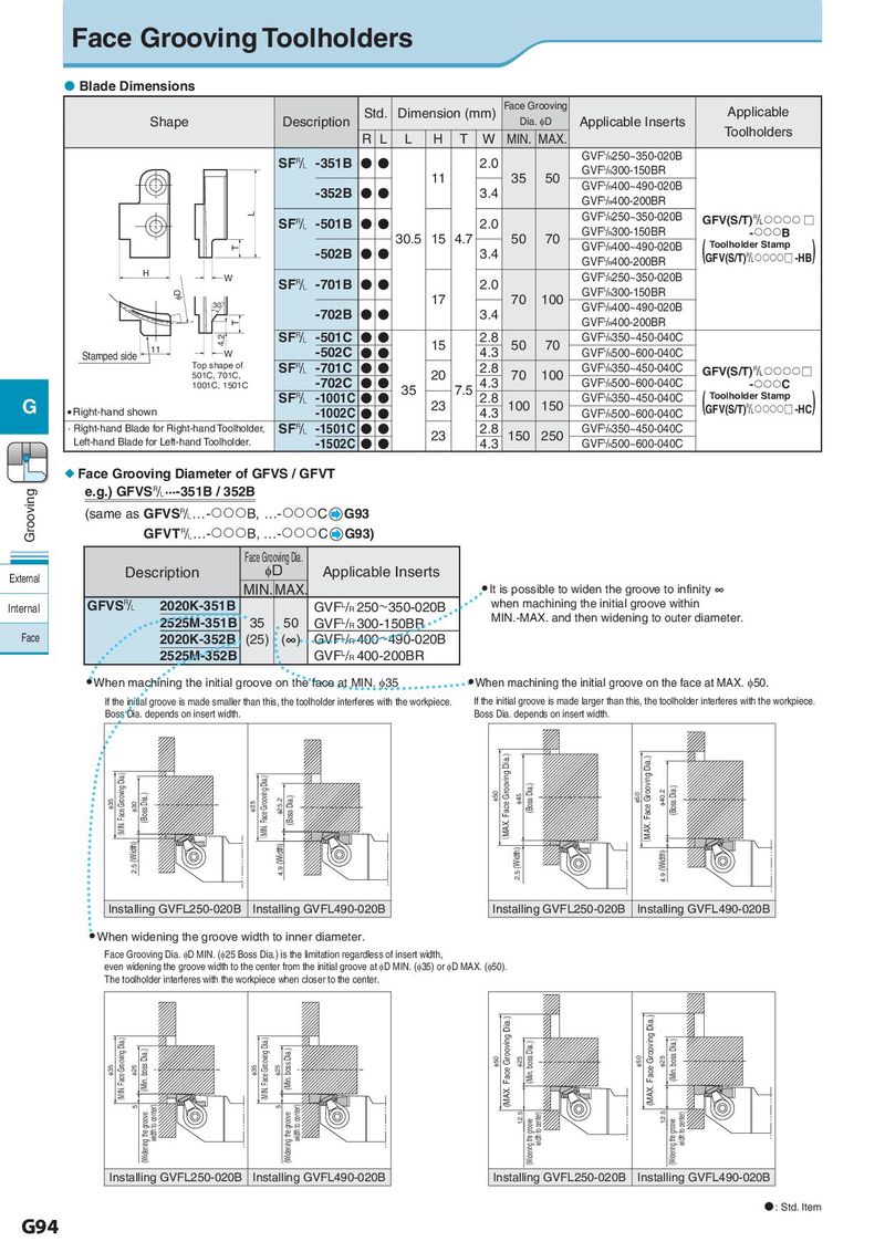
Face Grooving Toolholders Blade Dimensions Std. Dimension (mm) Face Grooving Applicable Shape Description Dia. φD Applicable Inserts R L L H T W MIN. MAX. Toolholders SF& -351B ●● 2.0 GVFL/R250~350-020B 11 35 50 GVFL/R300-150BR -352B ●● 3.4 GVFL/R400~490-020B GVFL/R400-200BR L GVFL/R250~350-020B GFV(S/T)& □ SF& -501B ●● 2.0 GVFL/R300-150BR -B T 30.5 15 4.7 50 70 GVFL/R400~490-020B ( ) Toolholder Stamp -502B ●● 3.4 GVFL/R400-200BR GFV(S/T)&□ -HB H W GVFL/R250~350-020B ID SF& -701B ●● 2.0 GVFL/R300-150BR 30° 17 70 100 GVFL/R400~490-020B T -702B ● ● 3.4 GVFL/R400-200BR 4.2 SF& -501C ● ● 15 2.8 50 70 GVFL/R350~450-040C Stamped side 11 W -502C ● ● 4.3 GVFL/R500~600-040C Top shape of SF& -701C ● ● 2.8 GVFL/R350~450-040C GFV(S/T)&□ 501C, 701C, -702C ● ● 20 4.3 70 100 GVFL/R500~600-040C -C 1001C, 1501C 35 7.5 G SF& -1001C ● ● 23 2.8 100 150 GVFL/R350~450-040C ( ) Toolholder Stamp Right-hand shown -1002C ● ● 4.3 GVFL/R500~600-040C GFV(S/T)&□ -HC · Right-hand Blade for Right-hand Toolholder, SF& -1501C ● ● 23 2.8 150 250 GVFL/R350~450-040C Left-hand Blade for Left-hand Toolholder. -1502C ● ● 4.3 GVFL/R500~600-040C Face Grooving Diameter of GFVS / GFVT Grooving e.g.) GFVS&···-351B / 352B (same as GFVS&…-B, …-C G93 GFVT&…-B, …-C G93) Face Grooving Dia. External Description ID Applicable Inserts MIN. MAX. ● It is possible to widen the groove to infinity ∞ Internal GFVS& 2020K-351B GVFL/R 250~350-020B when machining the initial groove within 2525M-351B 35 50 GVFL/R 300-150BR MIN.-MAX. and then widening to outer diameter. Face 2020K-352B (25) (∞) GVFL/R 400~490-020B 2525M-352B GVFL/R 400-200BR ● When machining the initial groove on the face at MIN. I35 ● When machining the initial groove on the face at MAX. I50. If the initial groove is made smaller than this, the toolholder interferes with the workpiece. If the initial groove is made larger than this, the toolholder interferes with the workpiece. Boss Dia. depends on insert width. Boss Dia. depends on insert width. I35 (MIN. Face Grooving Dia.) (Boss Dia.) I35 (MIN. Face Grooving Dia.) I25.2 (Boss Dia.) I50 (MAX. Face Grooving Dia.) I45 (Boss Dia.) I50 (MAX. Face Grooving Dia.) I40.2 (Boss Dia.) I30 2.5 (Width) 4.9 (Width) 2.5 (Width) 4.9 (Width) Installing GVFL250-020B Installing GVFL490-020B Installing GVFL250-020B Installing GVFL490-020B ● When widening the groove width to inner diameter. Face Grooving Dia. ID MIN. (I25 Boss Dia.) is the limitation regardless of insert width, even widening the groove width to the center from the initial groove at ID MIN. (I35) or ID MAX. (I50). The toolholder interferes with the workpiece when closer to the center. I35 (MIN. Face Grooving Dia.) I25 (Min. boss Dia.) I35 (MIN. Face Grooving Dia.) I25 (Min. boss Dia.) I50 (MAX. Face Grooving Dia.) I25 (Min. boss Dia.) I50 (MAX. Face Grooving Dia.) I25 (Min. boss Dia.) 5 width to center) 5 width to center) (Widening the groove (Widening the groove 12.5 (Widening the groove width to center) 12.5 (Widening the groove width to center) Installing GVFL250-020B Installing GVFL490-020B Installing GVFL250-020B Installing GVFL490-020B : Std. Item G94