Основной каталог Kyocera 2016-2017 - страница 449
Навигация
 Каталог Kyocera фрезы MFH для высокоскоростной обработки
 Каталог Kyocera фрезы MEC высокопроизводительные концевые и торцевые фрезы
 Каталог микроинструмента Kyocera 2015-2016
 Каталог Kyocera высокоэффективные сверла со сменными пластинами DRV
 Каталог Kyocera пластины TQ для нарезания резьбы c прессованным стружколомом
 Каталог Kyocera высокопроизводительные модульные сверла DRA
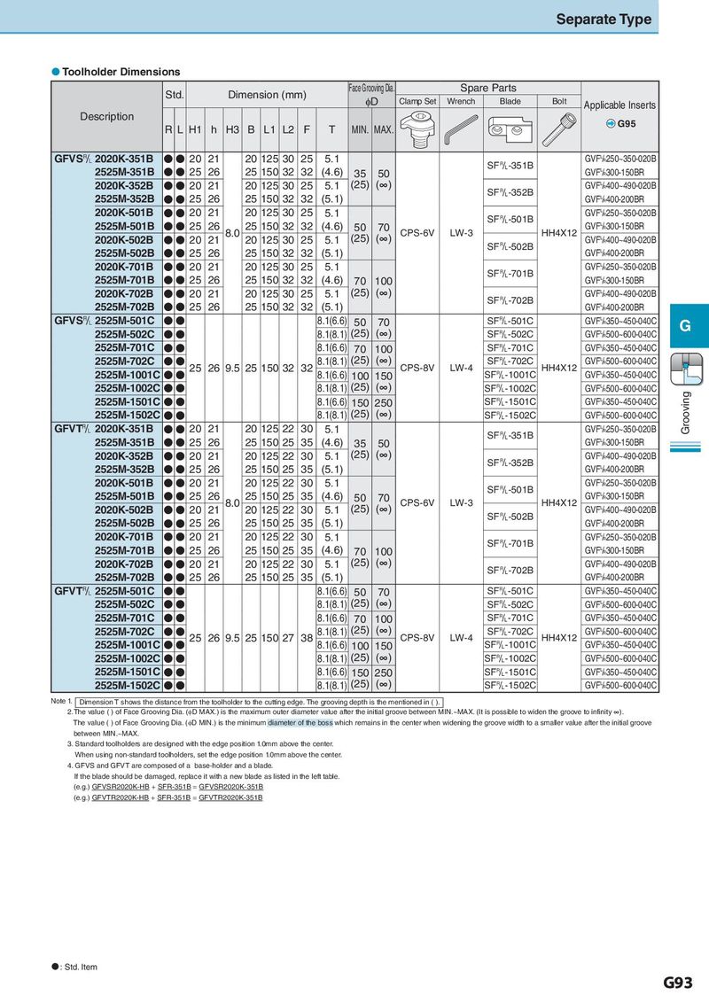
Separate Type Toolholder Dimensions Std. Dimension (mm) Face Grooving Dia. Spare Parts φD Clamp Set Wrench Blade Bolt Applicable Inserts Description G95 R L H1 h H3 B L1 L2 F T MIN. MAX. GFVS& 2020K-351B ● ● 20 21 20 125 30 25 5.1 SF&-351B GVFL/R250~350-020B 2525M-351B ● ● 25 26 25 150 32 32 (4.6) 35 50 GVFL/R300-150BR 2020K-352B ● ● 20 21 20 125 30 25 5.1 (25) (∞) SF&-352B GVFL/R400~490-020B 2525M-352B ● ● 25 26 25 150 32 32 (5.1) GVFL/R400-200BR 2020K-501B ● ● 20 21 20 125 30 25 5.1 SF&-501B GVFL/R250~350-020B 2525M-501B ● ● 25 26 8.0 25 150 32 32 (4.6) 50 70 CPS-6V LW-3 HH4X12 GVFL/R300-150BR 2020K-502B ● ● 20 21 20 125 30 25 5.1 (25) (∞) SF&-502B GVFL/R400~490-020B 2525M-502B ● ● 25 26 25 150 32 32 (5.1) GVFL/R400-200BR 2020K-701B ● ● 20 21 20 125 30 25 5.1 SF&-701B GVFL/R250~350-020B 2525M-701B ● ● 25 26 25 150 32 32 (4.6) 70 100 GVFL/R300-150BR 2020K-702B ● ● 20 21 20 125 30 25 5.1 (25) (∞) SF&-702B GVFL/R400~490-020B 2525M-702B ● ● 25 26 25 150 32 32 (5.1) GVFL/R400-200BR GFVS& 2525M-501C ● ● 8.1(6.6) 50 70 SF&-501C GVFL/R350~450-040C G 2525M-502C ● ● 8.1(8.1) (25) (∞) SF&-502C GVFL/R500~600-040C 2525M-701C ● ● 8.1(6.6) 70 100 SF&-701C GVFL/R350~450-040C 2525M-702C ● ● 25 26 9.5 25 150 32 32 8.1(8.1) (25) (∞) CPS-8V LW-4 SF&-702C HH4X12 GVFL/R500~600-040C 2525M-1001C ● ● 8.1(6.6) 100 150 SF&-1001C GVFL/R350~450-040C 2525M-1002C ● ● 8.1(8.1) (25) (∞) SF&-1002C GVFL/R500~600-040C Grooving 2525M-1501C ● ● 8.1(6.6) 150 250 SF&-1501C GVFL/R350~450-040C 2525M-1502C ● ● 8.1(8.1) (25) (∞) SF&-1502C GVFL/R500~600-040C GFVT& 2020K-351B ● ● 20 21 20 125 22 30 5.1 SF&-351B GVFL/R250~350-020B 2525M-351B ● ● 25 26 25 150 25 35 (4.6) 35 50 GVFL/R300-150BR 2020K-352B ● ● 20 21 20 125 22 30 5.1 (25) (∞) SF&-352B GVFL/R400~490-020B 2525M-352B ● ● 25 26 25 150 25 35 (5.1) GVFL/R400-200BR 2020K-501B ● ● 20 21 20 125 22 30 5.1 SF&-501B GVFL/R250~350-020B 2525M-501B ● ● 25 26 8.0 25 150 25 35 (4.6) 50 70 CPS-6V LW-3 HH4X12 GVFL/R300-150BR 2020K-502B ● ● 20 21 20 125 22 30 5.1 (25) (∞) SF&-502B GVFL/R400~490-020B 2525M-502B ● ● 25 26 25 150 25 35 (5.1) GVFL/R400-200BR 2020K-701B ● ● 20 21 20 125 22 30 5.1 SF&-701B GVFL/R250~350-020B 2525M-701B ● ● 25 26 25 150 25 35 (4.6) 70 100 GVFL/R300-150BR 2020K-702B ● ● 20 21 20 125 22 30 5.1 (25) (∞) SF&-702B GVFL/R400~490-020B 2525M-702B ● ● 25 26 25 150 25 35 (5.1) GVFL/R400-200BR GFVT& 2525M-501C ● ● 8.1(6.6) 50 70 SF&-501C GVFL/R350~450-040C 2525M-502C ● ● 8.1(8.1) (25) (∞) SF&-502C GVFL/R500~600-040C 2525M-701C ● ● 8.1(6.6) 70 100 SF&-701C GVFL/R350~450-040C 2525M-702C ● ● 25 26 9.5 25 150 27 38 8.1(8.1) (25) (∞) CPS-8V LW-4 SF&-702C HH4X12 GVFL/R500~600-040C 2525M-1001C ● ● 8.1(6.6) 100 150 SF&-1001C GVFL/R350~450-040C 2525M-1002C ● ● 8.1(8.1) (25) (∞) SF&-1002C GVFL/R500~600-040C 2525M-1501C ● ● 8.1(6.6) 150 250 SF&-1501C GVFL/R350~450-040C 2525M-1502C ● ● 8.1(8.1) (25) (∞) SF&-1502C GVFL/R500~600-040C Note1. Dimension T shows the distance from the toolholder to the cutting edge. The grooving depth is the mentioned in ( ). 2.The value ( ) of Face Grooving Dia. (φD MAX.) is the maximum outer diameter value after the initial groove between MIN.~MAX. (It is possible to widen the groove to infinity ∞). The value ( ) of Face Grooving Dia. (φD MIN.) is the minimum diameter of the boss which remains in the center when widening the groove width to a smaller value after the initial groove between MIN.~MAX. 3. Standard toolholders are designed with the edge position 1.0mm above the center. When using non-standard toolholders, set the edge position 1.0mm above the center. 4. GFVS and GFVT are composed of a base-holder and a blade. If the blade should be damaged, replace it with a new blade as listed in the left table. (e.g.) GFVSR2020K-HB + SFR-351B = GFVSR2020K-351B (e.g.) GFVTR2020K-HB + SFR-351B = GFVTR2020K-351B : Std. Item G93