Основной каталог Kyocera 2016-2017 - страница 444
Навигация
 Каталог Kyocera фрезы MFH для высокоскоростной обработки
 Каталог Kyocera фрезы MEC высокопроизводительные концевые и торцевые фрезы
 Каталог микроинструмента Kyocera 2015-2016
 Каталог Kyocera высокоэффективные сверла со сменными пластинами DRV
 Каталог Kyocera пластины TQ для нарезания резьбы c прессованным стружколомом
 Каталог Kyocera высокопроизводительные модульные сверла DRA
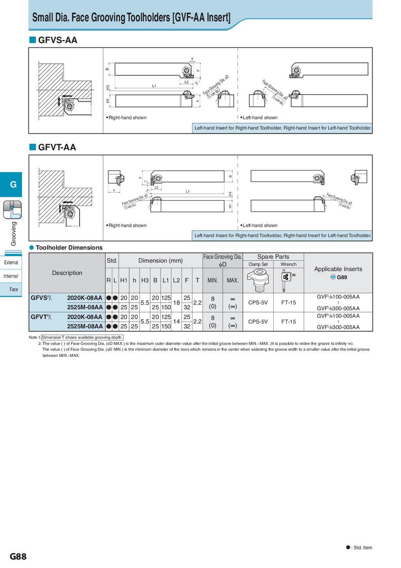
L2 2° Face(ToGoruoteorvdiian.)g Dia. ID Small Dia. Face Grooving Toolholders [GVF-AA Insert] H3 L1 H1 h GFVS-AA T B F L2 2° Face(ToGoruoteorvdiian.)g Dia. ID Face Gro(oTvoionugterDdiiaa..) ID H3 L1 H1 h Right-hand shown Left-hand shown F B T Left-hand Insert for Right-hand Toolholder, Right-hLa2nd Insert for Left-hand Toolholder. h 2° L1 H3 図-2 GFVT-AA Fa(cToeoGuterrodoiav.)ing Dia. ID H1 Face Gro(oTvoionugterDdiiaa..) ID B F G T h 2° L2 L1 H3 図-2 Face Groov(TinogouDteirad.iaI.)D 図-2 Fa(cToeoGuterrodoiav.)ing Dia. ID H1 Grooving Right-hand shown Left-hand shown Left-hand Insert for Right-hand Toolholder, Right-hand Insert for Left-hand Toolholder. Toolholder Dimensions Face 図-2 Std. Dimension (mm) Groov(TinogouDteiraFd.iaIa.)Dce Grooving Dia. Spare Parts External φD Clamp Set Wrench Description Applicable Inserts Internal R L H1 h H3 B L1 L2 F T MIN. MAX. G89 Face GFVS& 2020K-08AA ● ● 20 20 20 125 25 8 ∞ GVFL/R100-005AA 5.5 18 2.2 (0) (∞) CPS-5V FT-15 ~ 2525M-08AA ● ● 25 25 25 150 32 GVFL/R300-005AA GFVT& 2020K-08AA ● ● 20 20 20 125 25 8 ∞ GVFL/R100-005AA 5.5 14 2.2 (0) (∞) CPS-5V FT-15 ~ 2525M-08AA ● ● 25 25 25 150 32 GVFL/R300-005AA Note 1. Dimension T shows available grooving depth. 2.The value ( ) of Face Grooving Dia. (φD MAX.) is the maximum outer diameter value after the initial groove between MIN.~MAX. (It is possible to widen the groove to infinity ∞). The value ( ) of Face Grooving Dia. (φD MIN.) is the minimum diameter of the boss which remains in the center when widening the groove width to a smaller value after the initial groove between MIN.~MAX. : Std. Item G88