Основной каталог Kyocera 2016-2017 - страница 429
Навигация
 Каталог Kyocera фрезы MFH для высокоскоростной обработки
 Каталог Kyocera фрезы MEC высокопроизводительные концевые и торцевые фрезы
 Каталог микроинструмента Kyocera 2015-2016
 Каталог Kyocera высокоэффективные сверла со сменными пластинами DRV
 Каталог Kyocera пластины TQ для нарезания резьбы c прессованным стружколомом
 Каталог Kyocera высокопроизводительные модульные сверла DRA
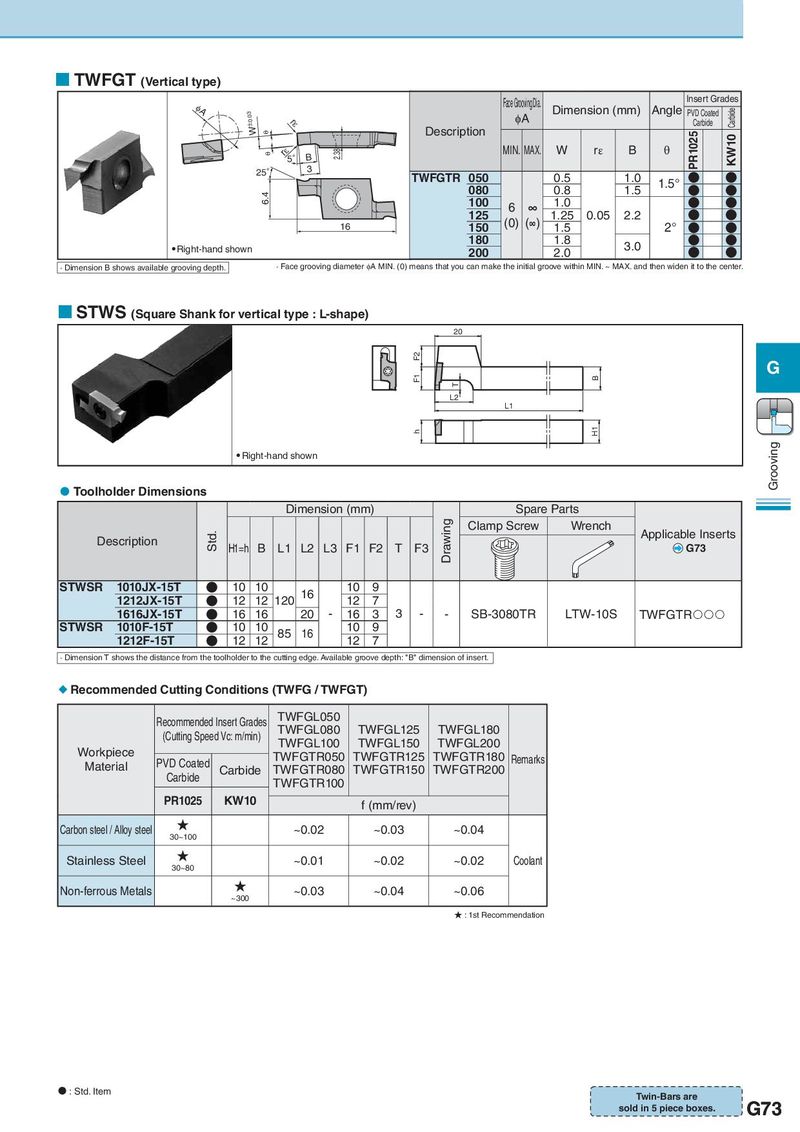
TWFGT (Vertical type) IA Face Grooving Dia. Insert Grades ±0.03 W φA Dimension (mm) Angle PVD Coated Carbide rH Description Carbide T PR1025 KW10 T rH5° B 2.38 MIN. MAX. W rε B θ 25° 3 TWFGTR 050 0.5 1.0 ● ● 080 0.8 1.5 1.5° ● ● 6.4 100 6 ∞ 1.0 ● ● 125 (0) (∞) 1.25 0.05 2.2 ● ● 16 150 1.5 2° ● ● Right-hand shown 180 1.8 3.0 ● ● 200 2.0 ● ● · Dimension B shows available grooving depth. · Face grooving diameter φA MIN. (0) means that you can make the initial groove within MIN. ~ MAX. and then widen it to the center. STWS (Square Shank for vertical type : L-shape) 20 F2 F1 B G T L2 L1 h H1 Right-hand shown Grooving Toolholder Dimensions Dimension (mm) Spare Parts Std. Drawing Clamp Screw Wrench Applicable Inserts Description H1=h B L1 L2 L3 F1 F2 T F3 G73 STWSR 1010JX-15T ● 10 10 16 10 9 1212JX-15T ● 12 12 120 12 7 1616JX-15T ● 16 16 20 - 16 3 3 - - SB-3080TR LTW-10S TWFGTR STWSR 1010F-15T ● 10 10 85 16 10 9 1212F-15T ● 12 12 12 7 · Dimension T shows the distance from the toolholder to the cutting edge. Available groove depth: "B" dimension of insert. Recommended Cutting Conditions (TWFG / TWFGT) Recommended Insert Grades TWFGL050 (Cutting Speed Vc: m/min) TWFGL080 TWFGL125 TWFGL180 Workpiece TWFGL100 TWFGL150 TWFGL200 Material PVD Coated TWFGTR050 TWFGTR125 TWFGTR180 Remarks Carbide Carbide TWFGTR080 TWFGTR150 TWFGTR200 TWFGTR100 PR1025 KW10 f (mm/rev) Carbon steel / Alloy steel ★ ~0.02 ~0.03 ~0.04 30~100 Stainless Steel ★ ~0.01 ~0.02 ~0.02 Coolant 30~80 Non-ferrous Metals ★ ~0.03 ~0.04 ~0.06 ~300 ★ : 1st Recommendation : Std. Item Twin-Bars are sold in 5 piece boxes. G73