Основной каталог Kyocera 2016-2017 - страница 426
Навигация
 Каталог Kyocera фрезы MFH для высокоскоростной обработки
 Каталог Kyocera фрезы MEC высокопроизводительные концевые и торцевые фрезы
 Каталог микроинструмента Kyocera 2015-2016
 Каталог Kyocera высокоэффективные сверла со сменными пластинами DRV
 Каталог Kyocera пластины TQ для нарезания резьбы c прессованным стружколомом
 Каталог Kyocera высокопроизводительные модульные сверла DRA
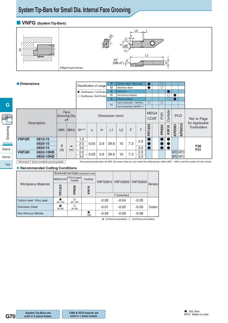
System Tip-Bars for Small Dia. Internal Face Grooving VNFG (System Tip-Bars) L2 1 IA rH T F W I8 rH L1 25° (NB=0°) H Right-hand shown Dimensions Classification of usage P Carbon steel / Alloy steel ● M Stainless Steel ● : Continuous / 1st Choice K Cast Iron ● : Continuous / 2nd Choice N Non-ferrous Metals ● S Titanium Alloys ● G H Hard materials (~40HRC) Hard materials (40HRC~) Face MEGA PVD Carbide Grooving Dia. Dimension (mm) COAT PCD Ref. to Page φA Description PR1225 PR930 KPD001 KPD010 for Applicable Grooving MIN. MAX. W±0.03 rε H L1 L2 F T KW10 Toolholders VNFGR 0810-10 1.0 2.0 ● ● ● 0820-10 8 ∞ 2.0 0.05 3.9 29.6 10 7.3 ● ● ● F30 External 0830-10 (0) (∞) 3.0 3.0 ● ● ● F31 VNFGR 0820-10NB 2.0 0.05 3.9 29.6 10 7.3 2.0 MTO MTO Internal 0830-10NB 3.0 3.0 MTO MTO · Dimension T shows available grooving depth. · Face grooving diameter φA MIN. (0) means that you can make the initial groove within MIN. ~ MAX. and then widen it to the center. Face Recommended Cutting Conditions Recommended Insert Grades (Cutting Speed Vc: m/min) MEGACOAT PVD Coated Carbide Carbide VNFG0810 VNFG0820 VNFG0830 Workpiece Material PR1225 PR930 KW10 Remarks f (mm/rev) Carbon steel / Alloy steel ★ ☆ ~0.02 ~0.04 ~0.05 30~100 30~100 Stainless Steel ★ ☆ ~0.01 ~0.02 ~0.03 Coolant 30~80 30~80 Non-ferrous Metals ★ ~0.04 ~0.06 ~0.08 ~300 ★ :1st Recommendation ☆ : 2nd Recommendation System Tip-Bars are CBN & PCD Inserts are : Std. Item G70 sold in 5 piece boxes. sold in 1 piece boxes. MTO : Made to order