Основной каталог Kyocera 2016-2017 - страница 417
Навигация
 Каталог Kyocera фрезы MFH для высокоскоростной обработки
 Каталог Kyocera фрезы MEC высокопроизводительные концевые и торцевые фрезы
 Каталог микроинструмента Kyocera 2015-2016
 Каталог Kyocera высокоэффективные сверла со сменными пластинами DRV
 Каталог Kyocera пластины TQ для нарезания резьбы c прессованным стружколомом
 Каталог Kyocera высокопроизводительные модульные сверла DRA
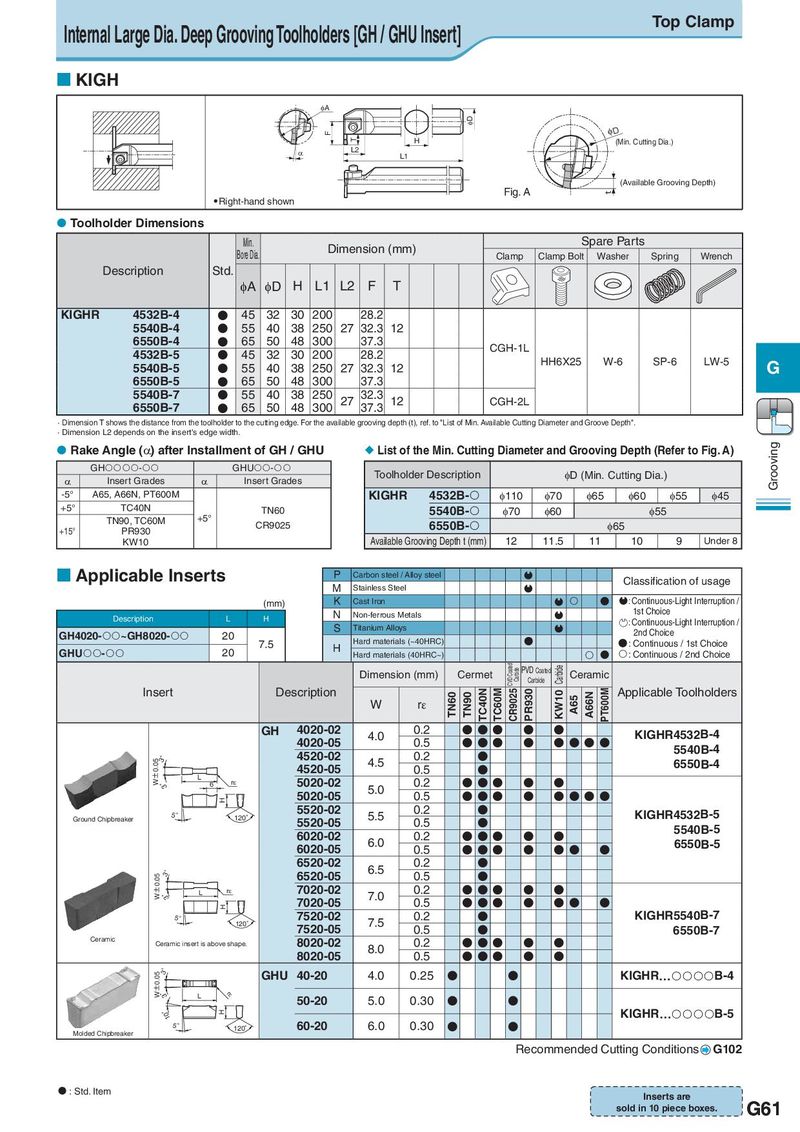
Internal Large Dia. Deep Grooving Toolholders [GH / GHU Insert] Top Clamp KIGH IA ID F ID T H (Min. Cutting Dia.) D L2 L1 (Available Grooving Depth) Fig. A t Right-hand shown Toolholder Dimensions Min. Dimension (mm) Spare Parts Bore Dia. 注) Clamp Clamp Bolt Washer Spring Wrench Description Std. φA φD H L1 L2 F T KIGHR 4532B-4 ● 45 32 30 200 28.2 5540B-4 ● 55 40 38 250 27 32.3 12 6550B-4 ● 65 50 48 300 37.3 CGH-1L 4532B-5 ● 45 32 30 200 28.2 HH6X25 W-6 SP-6 LW-5 5540B-5 ● 55 40 38 250 27 32.3 12 G 6550B-5 ● 65 50 48 300 37.3 5540B-7 ● 55 40 38 250 27 32.3 12 CGH-2L 6550B-7 ● 65 50 48 300 37.3 · Dimension T shows the distance from the toolholder to the cutting edge. For the available grooving depth (t), ref. to "List of Min. Available Cutting Diameter and Groove Depth". · Dimension L2 depends on the insert's edge width. Rake Angle (α) after Installment of GH / GHU List of the Min. Cutting Diameter and Grooving Depth (Refer to Fig. A) Grooving GH- GHU- Toolholder Description φD (Min. Cutting Dia.) α Insert Grades α Insert Grades -5° A65, A66N, PT600M KIGHR 4532B- φ110 φ70 φ65 φ60 φ55 φ45 +5° TC40N TN60 5540B- φ70 φ60 φ55 TN90, TC60M +5° CR9025 6550B- φ65 +15° PR930 KW10 Available Grooving Depth t (mm) 12 11.5 11 10 9 Under 8 Applicable Inserts P Carbon steel / Alloy steel Classification of usage M Stainless Steel (mm) K Cast Iron ● : Continuous-Light Interruption / Description L H N Non-ferrous Metals 1st Choice S Titanium Alloys : Continuous-Light Interruption / GH4020-~GH8020- 20 2nd Choice 7.5 H Hard materials (~40HRC) ● ● : Continuous / 1st Choice GHU- 20 Hard materials (40HRC~) ● : Continuous / 2nd Choice Dimension (mm) Cermet CVD Coated Carbide PVD Coated Carbide Ceramic Carbide Insert Description TN60 TN90 TC40N TC60M CR9025 PR930 KW10 A65 A66N PT600M Applicable Toolholders W rε GH 4020-02 4.0 0.2 ● ● ● ● ● KIGHR4532B-4 4020-05 0.5 ● ● ● ● ● ● ● ● KIGH&5540B-4 3W゜±0.035゜ 4520-02 4.5 0.2 ● KIGH&6550B-4 L 4520-05 0.5 ● 6 rH 5020-02 5.0 0.2 ● ● ● ● ● H 5020-05 0.5 ● ● ● ● ● ● ● ● 5゜ 120゜ 5520-02 5.5 0.2 ● KIGHR4532B-5 Ground Chipbreaker 5520-05 0.5 ● 6020-02 0.2 ● ● ● ● ● KIGH&5540B-5 6020-05 6.0 0.5 ● ● ● ● ● ● ● KIGH&6550B-5 3゜ 6520-02 6.5 0.2 ● W±0.05 6520-05 0.5 ● 3゜ L rH 7020-02 7.0 0.2 ● ● ● ● ● H 7020-05 0.5 ● ● ● ● ●● ● 5゜ 120゜ 7520-02 7.5 0.2 ● KIGHR5540B-7 7520-05 0.5 ● KIGH&6550B-7 Ceramic Ceramic insert is above shape. 8020-02 0.2 ● ● ● ● ● 8020-05 8.0 0.5 ● ● ● ● ● W±0.053゜ GHU 40-20 4.0 0.25 ● ● KIGHR…B-4 3゜ L rH 10゜ 50-20 5.0 0.30 ● ● H KIGHR…B-5 5゜ 120゜ 60-20 6.0 0.30 ● ● Molded Chipbreaker Recommended Cutting Conditions G102 : Std. Item Inserts are sold in 10 piece boxes. G61