Основной каталог Kyocera 2016-2017 - страница 412
Навигация
 Каталог Kyocera фрезы MFH для высокоскоростной обработки
 Каталог Kyocera фрезы MEC высокопроизводительные концевые и торцевые фрезы
 Каталог микроинструмента Kyocera 2015-2016
 Каталог Kyocera высокоэффективные сверла со сменными пластинами DRV
 Каталог Kyocera пластины TQ для нарезания резьбы c прессованным стружколомом
 Каталог Kyocera высокопроизводительные модульные сверла DRA
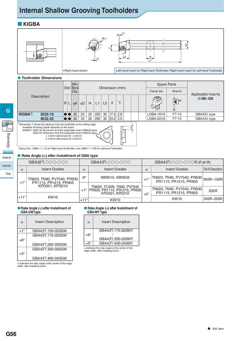
Internal Shallow Grooving Toolholders KIGBA 2° φA φD F T α L2 H L1 Right-hand shown Left-hand Insert for Right-hand Toolholder, Right-hand Insert for Left-hand Toolholder. Toolholder Dimensions Min. Spare Parts Std. Bore Dimension (mm) Dia. Clamp Set Wrench Description Applicable Inserts G6~G8 RL φA φD H L1 L2 F *T G KIGBA& 3525-16 ●● 35 25 23 220 30 17.5 2.8 LGBA-16L/RS FT-15 GBA32L/R type 4032-22 ●● 40 32 30 250 30 23.0 3.0 LGBA-22L/RS FT-15 GBA43L/R type *Dimension T shows the distance from the toolholder to the cutting edge. Available Grooving Depth depends on the insert. B KIGBA& 3525-16: Dimension B of the applicable insert (GBA32 type) Grooving 4032-22: Dimension B of the applicable insert (GBA43 type) 1. 2.0mm (Dimension B < 2.8mm) 2. 2.8mm (Dimension B ≥ 2.8mm) · Clamp Set : LGBA- LS for Right-hand Toolholder, and LGBA- RS for Left-hand Toolholder. External Rake Angle (α) after Installment of GBA type GBA32&- GBA43&- GBA43&-R (Full-R) Internal α Insert Grades α Insert Grades α Insert Grades Full-R Description Face TN620, TN90, PV7040, PR930 -9° KBN510, KBN525 +1° TN620, TN90, PV7040, PR930 050R~150R +1° PR1115, PR1215, PR905 PR1115, PR1215, PR905 KPD001, KPD010 TN620, TC40N, TN90, PV7040 TN620, TN90, PV7040, PR930 +1° PR930, PR1115, PR1215, PR905 PR1115, PR1215, PR905 200R KPD001, KPD010 +5° +11° KW10 +11° KW10 KW10 050R~200R Rake Angle (α) after Installment of Rake Angle (α) after Installment of GBA-GM type GBA-MY type α Insert Description α Insert Description +1° GBA43&150-020GM GBA43&175-020MY GBA43&175-020GM +6° ~ +6° ~ GBA43&350-030MY GBA43&265-030GM +5° GBA43&400-040MY GBA43&300-030GM α indicates the rake angle at the center of the edge width, after installing insert. +3° ~ GBA43&400-040GM α indicates the rake angle at the center of the edge width, after installing insert. : Std. Item G56