Основной каталог Kyocera 2016-2017 - страница 410
Навигация
 Каталог Kyocera фрезы MFH для высокоскоростной обработки
 Каталог Kyocera фрезы MEC высокопроизводительные концевые и торцевые фрезы
 Каталог микроинструмента Kyocera 2015-2016
 Каталог Kyocera высокоэффективные сверла со сменными пластинами DRV
 Каталог Kyocera пластины TQ для нарезания резьбы c прессованным стружколомом
 Каталог Kyocera высокопроизводительные модульные сверла DRA
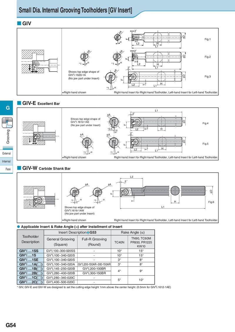
Small Dia. Internal Grooving Toolholders [GV Insert] GIV IA 2° F ID Fig.1 D T L2 H L1 IA IA 2° ID Fig.2 F D D T *1 *1 L2 H 2° L1 Shows top edge shape of IA GIV&1620-1A ID Fig.3 (No jaw part under Insert) F L2 T L1 H *1 D Right-hand shown Right-hand Insert for Right-hand Toolholder, Left-hand Insert for Left-hand Toolholder. GIV-E Excellent Bar G L1 IA 2° Shows top edge shape of ID GIV&1612-1AE Fig.4 (No jaw part under Insert) F Grooving *0.5 D L2 T H IA IA 2° ID Fig.5 F L2 T L1 H External *1 D *1 D Right-hand shown Right-hand Insert for Right-hand Toolholder, Left-hand Insert for Left-hand Toolholder. Internal Face GIV-W Carbide Shank Bar L2 2° IA IA F ID *1 D *1 D T H Fig.6 Shows top edge shape of L1 GIV&1616-1AW (No jaw part under Insert) Right-hand shown Right-hand Insert for Right-hand Toolholder, Left-hand Insert for Left-hand Toolholder. Applicable Insert & Rake Angle (α) after Installment of Insert Insert Description G53 Rake Angle (α) Toolholder General Grooving Full-R Grooving TN90, TC60M Description (Square) (Round) TC40N PR930, PR1225 KW10 GIV&…1SS GV&100~300-020SS - 10° 15° GIV&…1S GV&100~340-020S - 10° 15° GIV&…1SE GV&100~340-020S - 3° 8° GIV&…1A(□) GV&100~340-020A GV&200-100AR~300-150AR 3° 8° GIV&…1B(□) GV&145~250-020B GV&200-100BR 4° 9° GIV&…2B(□) GV&280~400-020B GV&300-150BR GIV&…1C(□) GV&280~340-020C - 5° 10° GIV&…2C(□) GV&400~500-020C - * GIV, GIV-E and GIV-W are designed to set the cutting edge height 1mm above the center height. (0.5mm for GIV&1612-1AE) G54