Основной каталог Kyocera 2016-2017 - страница 407
Навигация
 Каталог Kyocera фрезы MFH для высокоскоростной обработки
 Каталог Kyocera фрезы MEC высокопроизводительные концевые и торцевые фрезы
 Каталог микроинструмента Kyocera 2015-2016
 Каталог Kyocera высокоэффективные сверла со сменными пластинами DRV
 Каталог Kyocera пластины TQ для нарезания резьбы c прессованным стружколомом
 Каталог Kyocera высокопроизводительные модульные сверла DRA
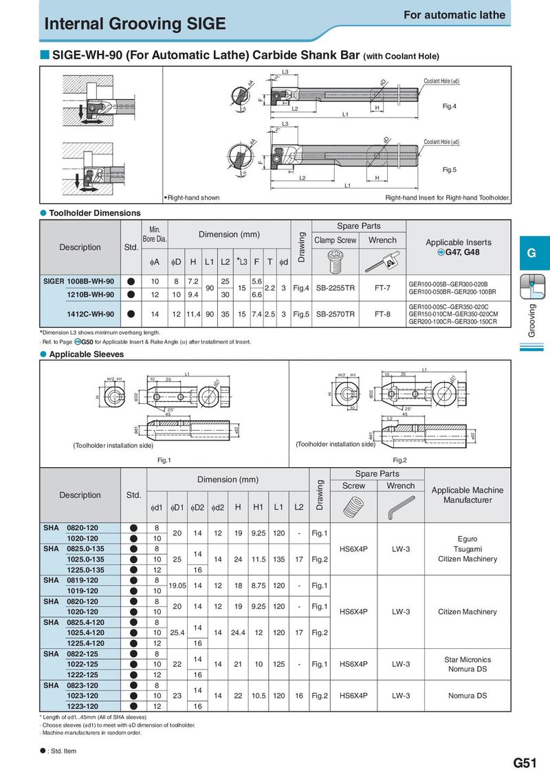
Internal Grooving SIGE For automatic lathe SIGE-WH-90 (For Automatic Lathe) Carbide Shank Bar (with Coolant Hole) L3 2° Coolant Hole (φd) φA φD F T α L2 H Fig.4 L1 L3 2° φA φD Coolant Hole (φd) F α T Fig.5 L2 H L1 Right-hand shown Right-hand Insert for Right-hand Toolholder. Toolholder Dimensions Min. Spare Parts Bore Dia. Dimension (mm) Drawing Clamp Screw Wrench Description Std. Applicable Inserts G47, G48 G φA φD H L1 L2 *L3 F T φd SIGER 1008B-WH-90 ● 10 8 7.2 90 25 15 5.6 2.2 3 Fig.4 SB-2255TR FT-7 GER100-005B~GER300-020B 1210B-WH-90 ● 12 10 9.4 30 6.6 GER100-050BR~GER200-100BR GER100-005C~GER350-020C Grooving 1412C-WH-90 ● 14 12 11.4 90 35 15 7.4 2.5 3 Fig.5 SB-2570TR FT-8 GER150-010CM~GER350-020CM GER200-100CR~GER300-150CR *Dimension L3 shows minimum overhang length. · Ref. to Page G50 for Applicable Insert & Rake Angle (α) after Installment of Insert. Applicable Sleeves L1 L1 H/2 H1 10 25 φD1 H/2 H1 10 25 φD1 φD2 H φD2 H 25° 10 25° 45 45 L2 φd1 φd2 φd1 φd2 (Toolholder installation side) (Toolholder installation side) Fig.1 Fig.2 Dimension (mm) Spare Parts Drawing Screw Wrench Applicable Machine Description Std. Manufacturer φd1 φD1 φD2 φd2 H H1 L1 L2 SHA 0820-120 ● 8 20 14 12 19 9.25 120 - Fig.1 1020-120 ● 10 Eguro SHA 0825.0-135 ● 8 14 HS6X4P LW-3 Tsugami 1025.0-135 ● 10 25 14 24 11.5 135 17 Fig.2 Citizen Machinery 1225.0-135 ● 12 16 SHA 0819-120 ● 8 19.05 14 12 18 8.75 120 - Fig.1 1019-120 ● 10 SHA 0820-120 ● 8 20 14 12 19 9.25 120 - Fig.1 1020-120 ● 10 HS6X4P LW-3 Citizen Machinery SHA 0825.4-120 ● 8 14 1025.4-120 ● 10 25.4 14 24.4 12 120 17 Fig.2 1225.4-120 ● 12 16 SHA 0822-125 ● 8 14 Star Micronics 1022-125 ● 10 22 14 21 10 125 - Fig.1 HS6X4P LW-3 Nomura DS 1222-125 ● 12 16 SHA 0823-120 ● 8 14 1023-120 ● 10 23 14 22 10.5 120 16 Fig.2 HS6X4P LW-3 Nomura DS 1223-120 ● 12 16 * Length of φd1...45mm (All of SHA sleeves) · Choose sleeves (φd1) to meet with φD dimension of toolholder. · Machine manufacturers in random order. : Std. Item G51