Основной каталог Kyocera 2016-2017 - страница 382
Навигация
 Каталог Kyocera фрезы MFH для высокоскоростной обработки
 Каталог Kyocera фрезы MEC высокопроизводительные концевые и торцевые фрезы
 Каталог микроинструмента Kyocera 2015-2016
 Каталог Kyocera высокоэффективные сверла со сменными пластинами DRV
 Каталог Kyocera пластины TQ для нарезания резьбы c прессованным стружколомом
 Каталог Kyocera высокопроизводительные модульные сверла DRA
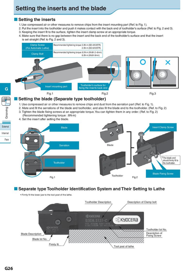
Setting the inserts and the blade Setting the inserts 1. Use compressed air or other measures to remove chips from the insert mounting part (Ref. to Fig. 1). 2. Put the insert into the toolholder and push it makes contact with the back end of toolholder's surface (Ref. to Fig. 2 and 3). 3. Keeping the insert fit to the surface, tighten the insert clamp screw at an appropriate torque. 4. Make sure that there is no gap between the insert and the back end of the toolholder’s surface and that the insert is set straight (Ref. to Fig. 2 and 3). Clamp Screw Recommended tightening torque: 2.0N·m (SB-40120TR) (For Automatic Lathe) 2.5N·m (SE-50125TR) Clamp Bolt Recommended tightening torque: 6.5N·m (Width 2~6mm) 8.0N·m (Width 8mm) Insert mounting part Toolholder’s surface for G fixing the inserts back end Fig.1 Fig.2 Fig.3 Setting the blade (Separate type toolholder) 1. Use compressed air or other measures to remove chips and dust from the serration part (Ref. to Fig. 1). Grooving 2. Mate and fit the serrations of the blade and toolholder, and also fit the blade end to the toolholder. (Ref. to Fig. 2) 3. Tighten the blade fixing screws at an appropriate torque. You can tighten them in any order. (Ref. to Fig. 2) (Recommended tightening torque : 8N·m) 4. Set the insert after setting the blade. External Blade Insert Clamp Screw Internal Face Serration Blade The blade end should firmly fit to Toolholder the toolholder. Toolholder Blade Fixing Screw Fig.1 Fig.2 Separate type Toolholder Identification System and Their Setting to Lathe • Firmly fit the lower jaw to the tool post of the lathe. Toolholder Description Description of Clamp bolt Toolholder lot No. Blade Description Description of Fixing Screw Blade lot No. Firmly fit Tool post of lathe G26