Основной каталог Kyocera 2016-2017 - страница 375
Навигация
 Каталог Kyocera фрезы MFH для высокоскоростной обработки
 Каталог Kyocera фрезы MEC высокопроизводительные концевые и торцевые фрезы
 Каталог микроинструмента Kyocera 2015-2016
 Каталог Kyocera высокоэффективные сверла со сменными пластинами DRV
 Каталог Kyocera пластины TQ для нарезания резьбы c прессованным стружколомом
 Каталог Kyocera высокопроизводительные модульные сверла DRA
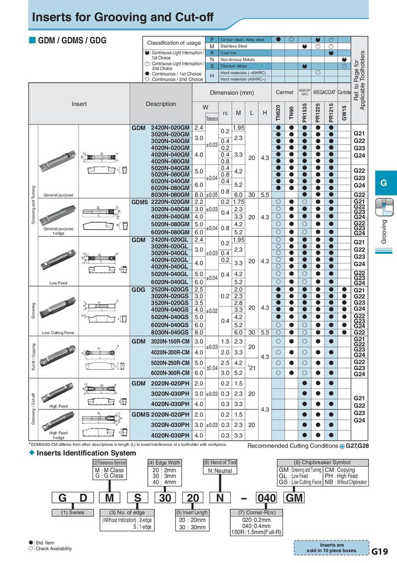
Inserts for Grooving and Cut-off GDM / GDMS / GDG Classification of usage P Carbon steel / Alloy steel M Stainless Steel : Continuous-Light Interruption / K Cast Iron Applicable Toolholders 1st Choice N Non-ferrous Metals Ref. to Page for : Continuous-Light Interruption / S Titanium Alloys 2nd Choice : Continuous / 1st Choice H Hard materials (~40HRC) : Continuous / 2nd Choice Hard materials (40HRC~) Dimension (mm) Cermet MEGACOAT MEGACOAT Carbide NANO Insert Description W TN620 TN90 PR1535 PR1225 PR1215 GW15 rε M L H Tolerance GDM 2420N-020GM 2.4 0.2 1.95 3020N-020GM 3.0 2.3 G21 3020N-040GM ±0.03 0.4 G22 4020N-020GM 0.2 G23 2° M rε 4020N-040GM 4.0 0.4 3.3 G24 W 20 4.3 2° L rε 4020N-080GM 0.8 H 5020N-040GM 5.0 0.4 4.2 G22 5020N-080GM ±0.04 0.8 G23 6020N-040GM 6.0 0.4 5.2 G24 G Turning 6020N-080GM 0.8 General purpose 8030N-080GM 8.0 ±0.05 6.0 30 5.5 G22 Grooving and GDMS 2220N-020GM 2.2 0.2 1.75 G21 G22 M 2° W 2° 3020N-040GM 3.0 ±0.03 2.3 L 4020N-040GM 4.0 0.4 3.3 G23 G24 rε 20 4.3 H 5020N-080GM 5.0 ±0.04 0.8 4.2 G22 Grooving G23 General purpose 6020N-080GM 6.0 5.2 1-edge G24 GDM 2420N-020GL 2.4 0.2 1.95 G21 3020N-020GL 3.0 2.3 G22 1.5° M rε 3020N-040GL ±0.03 0.4 G23 W 4020N-020GL 0.2 20 4.3 1.5° L 4.0 3.3 G24 H 4020N-040GL 5020N-040GL 5.0 ±0.04 0.4 4.2 G22 G23 6020N-040GL 6.0 5.2 G24 Low Feed GDG 2520N-020GS 2.5 2.0 G21 3020N-020GS 3.0 0.2 2.3 G22 2° M rε 3520N-020GS 3.5 2.8 G23 Grooving W 20 4.3 G24 2° L 4020N-040GS 4.0 ±0.02 3.3 20° 5020N-040GS 5.0 4.2 G22 H 0.4 G23 6020N-040GS 6.0 5.2 G24 Low Cutting Force 8030N-040GS 8.0 6.0 30 5.5 G22 GDM 3020N-150R-CM 3.0 1.5 2.3 G21 G22 Copying rε ±0.03 20 G23 M W 4020N-200R-CM 4.0 2.0 3.3 G24 / L 4.3 Full-R 5020N-250R-CM 5.0 2.5 4.2 *21 G22 H ±0.04 G23 6020N-300R-CM 6.0 3.0 5.2 G24 1.5° M rε GDM 2020N-020PH 2.0 0.2 1.5 W Cut-off 1.5° L rε 3020N-030PH 3.0 ±0.03 0.3 2.3 20 H G21 / High Feed 4020N-030PH 4.0 0.3 3.3 G22 Grooving M GDMS 2020N-020PH 2.0 0.2 1.5 4.3 G23 1.5° W G24 L 1.5° 3020N-030PH 3.0 ±0.03 0.3 2.3 20 rε High Feed H 4020N-030PH 4.0 0.3 3.3 1-edge *GDM50/60-CM differes from other descriptions in length (L) to avoid interference of a toolholder with workpiece. Recommended Cutting Conditions G27,G28 Inserts Identification System (2)Tolerance Symbol (4) Edge Width (6) Hand of Tool (8) Chipbreaker Symbol M㸯M Class 20㸯2mm N : Neutral GM㸯Grooving and Turning CM㸯Copying G㸯G Class 30㸯3mm GL 㸯Low Feed PH 㸯High Feed 40㸯4mm GS 㸯Low Cutting Force NB 㸯Without Chipbreaker G D M S 30 20 N - 040 GM (1) Series (3) No. of edge (5) Insert Length (7) Corner-R(rε) (Without Indication) : 2-edge 20㸯20mm 020㸯0.2mm S : 1-edge 30㸯30mm 040㸯0.4mm 150R㸯1.5mm(Full-R) : Std. Item Inserts are : Check Availability sold in 10 piece boxes. G19