Основной каталог Kyocera 2016-2017 - страница 298
Навигация
 Каталог Kyocera фрезы MFH для высокоскоростной обработки
 Каталог Kyocera фрезы MEC высокопроизводительные концевые и торцевые фрезы
 Каталог микроинструмента Kyocera 2015-2016
 Каталог Kyocera высокоэффективные сверла со сменными пластинами DRV
 Каталог Kyocera пластины TQ для нарезания резьбы c прессованным стружколомом
 Каталог Kyocera высокопроизводительные модульные сверла DRA
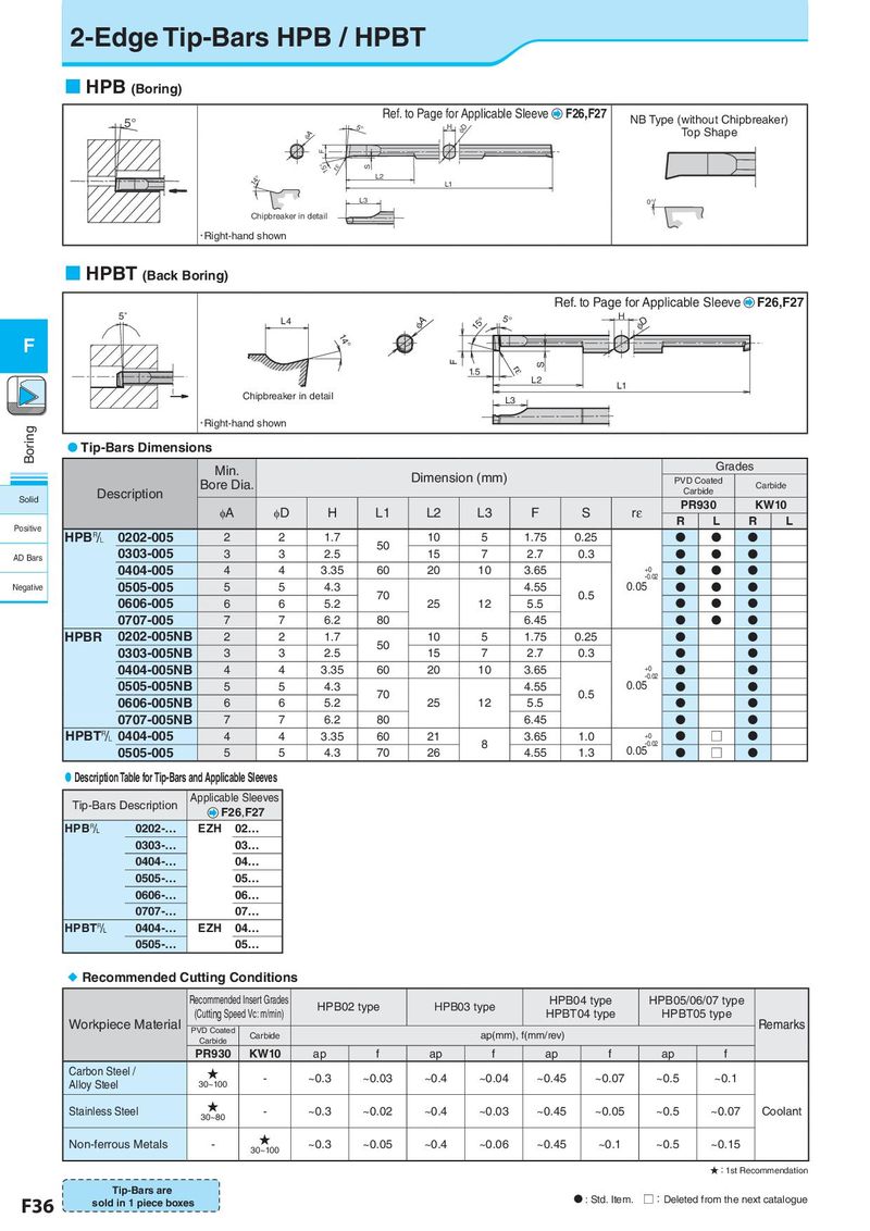
2-Edge Tip-Bars HPB / HPBT HPB (Boring) 5° Ref. to Page for Applicable Sleeve F26,F27 NB Type (without Chipbreaker) 5° H φD Top Shape φA F 15° rε S 14° L2 L1 L3 0° Chipbreaker in detail • Right-hand shown HPBT (Back Boring) Ref. to Page for Applicable Sleeve F26,F27 5° L4 φA 15° 5° H φD F 14° F S 1.5 rε L2 L1 Chipbreaker in detail L3 Boring • Right-hand shown Tip-Bars Dimensions Min. Grades Bore Dia. Dimension (mm) PVD Coated Carbide Description Carbide Solid PR930 KW10 φA φD H L1 L2 L3 F S rε R L R L Positive HPB& 0202-005 2 2 1.7 10 5 1.75 0.25 50 N N N AD Bars 0303-005 3 3 2.5 15 7 2.7 0.3 N N N 0404-005 4 4 3.35 60 20 10 3.65 +0 N N N -0.02 Negative 0505-005 5 5 4.3 70 4.55 0.5 0.05 N N N 0606-005 6 6 5.2 25 12 5.5 N N N 0707-005 7 7 6.2 80 6.45 N N N HPBR 0202-005NB 2 2 1.7 50 10 5 1.75 0.25 N N 0303-005NB 3 3 2.5 15 7 2.7 0.3 N N 0404-005NB 4 4 3.35 60 20 10 3.65 +0 N N -0.02 0505-005NB 5 5 4.3 70 4.55 0.5 0.05 N N 0606-005NB 6 6 5.2 25 12 5.5 N N 0707-005NB 7 7 6.2 80 6.45 N N HPBT& 0404-005 4 4 3.35 60 21 3.65 1.0 +0 N □ N 8 -0.02 0.05 0505-005 5 5 4.3 70 26 4.55 1.3 N □ N Description Table for Tip-Bars and Applicable Sleeves Tip-Bars Description Applicable Sleeves F26,F27 HPB& 0202-… EZH 02… 0303-… 03… 0404-… 04… 0505-… 05… 0606-… 06… 0707-… 07… HPBT& 0404-… EZH 04… 0505-… 05… Recommended Cutting Conditions Recommended Insert Grades HPB02 type HPB03 type HPB04 type HPB05/06/07 type Workpiece Material (Cutting Speed Vc: m/min) HPBT04 type HPBT05 type Remarks PVD Coated Carbide ap(mm), f(mm/rev) Carbide PR930 KW10 ap f ap f ap f ap f Carbon Steel / ★ - ~0.3 ~0.03 ~0.4 ~0.04 ~0.45 ~0.07 ~0.5 ~0.1 Alloy Steel 30~100 Stainless Steel ★ - ~0.3 ~0.02 ~0.4 ~0.03 ~0.45 ~0.05 ~0.5 ~0.07 Coolant 30~80 Non-ferrous Metals - ★ ~0.3 ~0.05 ~0.4 ~0.06 ~0.45 ~0.1 ~0.5 ~0.15 30~100 ★:1st Recommendation Tip-Bars are N : Std. Item. □:Deleted from the next catalogue F36 sold in 1 piece boxes