Основной каталог Kyocera 2016-2017 - страница 290
Навигация
 Каталог Kyocera фрезы MFH для высокоскоростной обработки
 Каталог Kyocera фрезы MEC высокопроизводительные концевые и торцевые фрезы
 Каталог микроинструмента Kyocera 2015-2016
 Каталог Kyocera высокоэффективные сверла со сменными пластинами DRV
 Каталог Kyocera пластины TQ для нарезания резьбы c прессованным стружколомом
 Каталог Kyocera высокопроизводительные модульные сверла DRA
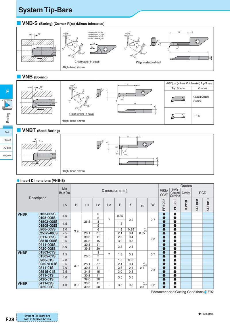
System Tip-Bars VNB-S (Boring) [Corner-R(rε) :Minus tolerance] 7° VNBR01{{-005S 7° L2 1 10° VNBR015{{-005S 10° VNBR015{{-01S 10° shows below figure φA 30° L3 30° F W L2 W rε rε rε S L1 15° 18° H Chipbreaker in detail Chipbreaker in detail • Right-hand shown VNB (Boring) 7° L2 1 −NB Type (without Chipbreaker) Top Shape 10° 10° Top Shape Grades F φA F θ Coated Carbide W rε S Carbide rε L1 H 18° Boring Chipbreaker in detail PCD • Right-hand shown Solid VNBT (Back Boring) L2 1 Positive 5° φA F AD Bars 15° 5° S Negative 2.0 rε L1 H • Right-hand shown Insert Dimensions (VNB-S) Min. Grades Bore Dia. Dimension (mm) MEGA PVD Coated Carbide PCD COAT Carbide Description PR1225 PR930 KPD001 KPD010 φA H L1 L2 L3 F S rε W KW10 VNBR 0103-005S 1.0 3 0.85 ● ● 0105-005S 5 7 0.2 0.7 ● ● 01503-005S 1.5 26.5 3 1.3 ● ● 01505-005S 5 ● ● 0206-005S 2.0 6 1.8 0.25 +0 ● ● 3.9 -0.02 025075-005S 2.5 28.1 7.5 2.1 0.4 0.05 ● ● 0311-005S 3.0 30.8 11 - 2.6 0.4 0.8 ● ● 03515-005S 3.5 34.8 15 3.0 0.5 ● ● 0411-005S 4.0 30.8 11 3.5 0.5 ● ● 0420-005S 39.8 20 ● ● VNBR 01503-01S 1.5 3 7 1.3 0.2 0.7 ● ● 01505-01S 26.5 5 ● ● 0206-01S 2.0 6 1.8 0.25 ● ● 025075-01S 2.5 28.1 7.5 2.1 0.4 +0 ● ● 3.9 -0.03 0311-01S 3.0 30.8 11 - 2.6 0.4 0.1 0.8 ● ● 03515-01S 3.5 34.8 15 3.0 0.5 ● ● 0411-01S 4.0 30.8 11 3.5 0.5 ● ● 0420-01S 39.8 20 ● ● VNBR 0411-02S 30.8 11 +0 ● ● 4.0 3.9 - 3.5 0.5 -0.04 0.8 0420-02S 39.8 20 0.2 ● ● Recommended Cutting Conditions F92 System Tip-Bars are N : Std. Item F28 sold in 5 piece boxes