Основной каталог Kyocera 2016-2017 - страница 287
Навигация
 Каталог Kyocera фрезы MFH для высокоскоростной обработки
 Каталог Kyocera фрезы MEC высокопроизводительные концевые и торцевые фрезы
 Каталог микроинструмента Kyocera 2015-2016
 Каталог Kyocera высокоэффективные сверла со сменными пластинами DRV
 Каталог Kyocera пластины TQ для нарезания резьбы c прессованным стружколомом
 Каталог Kyocera высокопроизводительные модульные сверла DRA
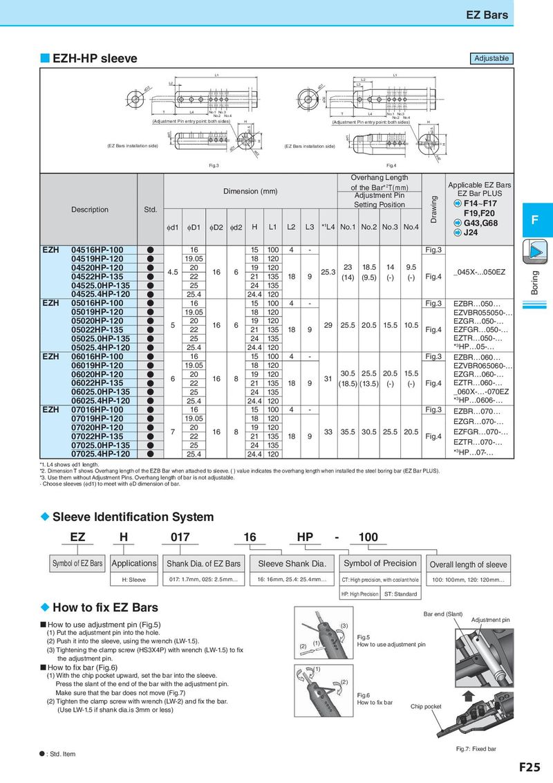
EZ Bars EZH-HP sleeve Adjustable L1 L1 L2 L2 φD1 L3 φD2 φD2 T L4 No.1 No.3 T L4 No.1 No.3 No.2 No.4 No.2 No.4 (Adjustment Pin entry point: both sides) H (Adjustment Pin entry point: both sides) H φd1 φ2.5 φ2.5 H φd1 (EZ Bars installation side) (EZ Bars installation side) H φD1 φd2 φd2 Fig.3 Fig.4 Overhang Length Dimension (mm) of the Bar*2T(mm) Applicable EZ Bars Adjustment Pin Drawing EZ Bar PLUS Description Std. Setting Position F14~F17 F19,F20 F φd1 φD1 φD2 φd2 H L1 L2 L3 *1L4 No.1 No.2 No.3 No.4 G43,G68 J24 EZH 04516HP-100 ● 16 15 100 4 - Fig.3 04519HP-120 ● 19.05 18 120 04520HP-120 ● 4.5 20 16 6 19 120 25.3 23 18.5 14 9.5 _045X-...050EZ 04522HP-135 ● 22 21 135 18 9 (14) (9.5) (-) (-) Fig.4 Boring 04525.0HP-135 ● 25 24 135 04525.4HP-120 ● 25.4 24.4 120 EZH 05016HP-100 ● 16 15 100 4 - Fig.3 EZBR…050… 05019HP-120 ● 19.05 18 120 EZVBR055050-… 05020HP-120 ● 5 20 16 6 19 120 29 25.5 20.5 15.5 10.5 EZGR…050-… 05022HP-135 ● 22 21 135 18 9 Fig.4 EZFGR…050-… 05025.0HP-135 ● 25 24 135 EZTR…050-… 05025.4HP-120 ● 25.4 24.4 120 *3HP…05-… EZH 06016HP-100 ● 16 15 100 4 - Fig.3 EZBR…060… 06019HP-120 ● 19.05 18 120 EZVBR065060-… 06020HP-120 ● 6 20 16 8 19 120 31 30.5 25.5 20.5 15.5 EZGR…060-… 06022HP-135 ● 22 21 135 18 9 (18.5) (13.5) (-) (-) Fig.4 EZTR…060-… 06025.0HP-135 ● 25 24 135 _060X-…-070EZ 06025.4HP-120 ● 25.4 24.4 120 *3HP…0606-… EZH 07016HP-100 ● 16 15 100 4 - Fig.3 EZBR…070… 07019HP-120 ● 19.05 18 120 EZGR…070-… 07020HP-120 ● 7 20 16 8 19 120 33 35.5 30.5 25.5 20.5 EZFGR…070-… 07022HP-135 ● 22 21 135 18 9 Fig.4 EZTR…070-… 07025.0HP-135 ● 25 24 135 07025.4HP-120 ● 25.4 24.4 120 *3HP…07-… *1. L4 shows φd1 length. *2. Dimension T shows Overhang length of the EZB Bar when attached to sleeve. ( ) value indicates the overhang length when installed the steel boring bar (EZ Bar PLUS). *3. Use them without Adjustment Pins. Overhang length of bar is not adjustable. · Choose sleeves (φd1) to meet with φD dimension of bar. CT: High precision, with coolant hole Sleeve Identification System EZ H 017 16 HP - 100 Symbol of EZ Bars Applications Shank Dia. of EZ Bars Sleeve Shank Dia. Symbol of Precision Overall length of sleeve H: Sleeve 017: 1.7mm, 025: 2.5mm… 16: 16mm, 25.4: 25.4mm… CT: High precision, with coolant hole 100: 100mm, 120: 120mm… HP: High Precision ST: Standard How to fix EZ Bars Bar end (Slant) How to use adjustment pin (Fig.5) Adjustment pin (3) (1) Put the adjustment pin into the hole. Fig.5 (2) Push it into the sleeve, using the wrench (LW-1.5). (2) (1) How to use adjustment pin (3) Tightening the clamp screw (HS3X4P) with wrench (LW-1.5) to fix the adjustment pin. How to fix bar (Fig.6) (1) (1) With the chip pocket upward, set the bar into the sleeve. Press the slant of the end of the bar with the adjustment pin. (2) Make sure that the bar does not move (Fig.7) Fig.6 (2) Tighten the clamp screw with wrench (LW-2) and fix the bar. How to fix bar Chip pocket (Use LW-1.5 if shank dia.is 3mm or less) N : Std. Item Fig.7: Fixed bar F25