Основной каталог Kyocera 2016-2017 - страница 268
Навигация
 Каталог Kyocera фрезы MFH для высокоскоростной обработки
 Каталог Kyocera фрезы MEC высокопроизводительные концевые и торцевые фрезы
 Каталог микроинструмента Kyocera 2015-2016
 Каталог Kyocera высокоэффективные сверла со сменными пластинами DRV
 Каталог Kyocera пластины TQ для нарезания резьбы c прессованным стружколомом
 Каталог Kyocera высокопроизводительные модульные сверла DRA
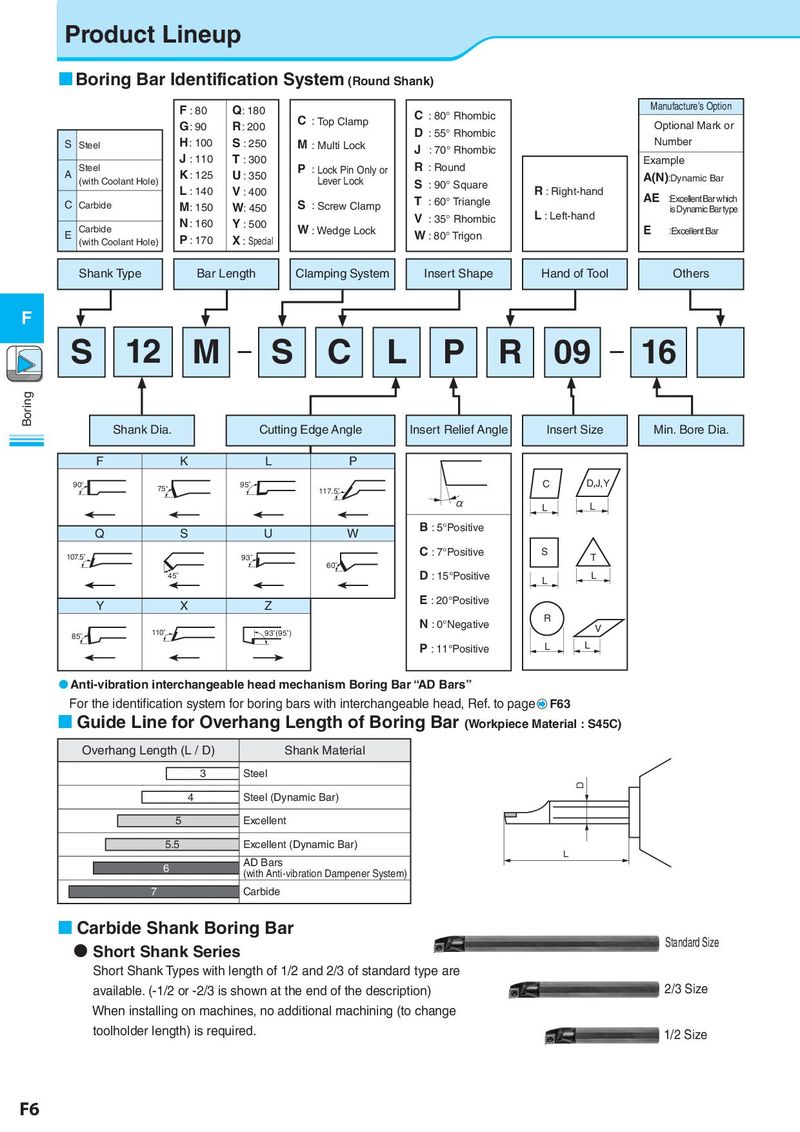
Product Lineup Boring Bar Identification System (Round Shank) F : 80 Q: 180 C Manufacture's Option C : Top Clamp : 80° Rhombic G: 90 R: 200 D : 55° Rhombic Optional Mark or S Steel H: 100 S : 250 M : Multi Lock J : 70° Rhombic Number Steel J : 110 T : 300 P R : Round Example A K : 125 U : 350 : Lock Pin Only or A(N):Dynamic Bar (with Coolant Hole) Lever Lock S : 90° Square L : 140 V : 400 T R : Right-hand AE :Excellent Bar which C Carbide M: 150 W: 450 S : Screw Clamp : 60° Triangle is Dynamic Bar type N : 160 Y : 500 V : 35° Rhombic L : Left-hand E Carbide W : Wedge Lock W : 80° Trigon E :Excellent Bar (with Coolant Hole) P : 170 X : Special Shank Type Bar Length Clamping System Insert Shape Hand of Tool Others F S 12 M − S C L P R 09 − 16 Boring Shank Dia. Cutting Edge Angle Insert Relief Angle Insert Size Min. Bore Dia. F K L P 90° 75° 95° 117.5° C D,J,Y α L L Q S U W B : 5°Positive 107.5° 93° C : 7°Positive S T 60° 45° D : 15°Positive L L Y X Z E : 20°Positive N : 0°Negative R 110° 93°(95°) V 85° P : 11°Positive L L Anti-vibration interchangeable head mechanism Boring Bar “AD Bars” For the identification system for boring bars with interchangeable head, Ref. to page F63 Guide Line for Overhang Length of Boring Bar (Workpiece Material : S45C) Overhang Length (L / D) Shank Material 3 Steel D 4 Steel (Dynamic Bar) 5 Excellent 5.5 Excellent (Dynamic Bar) AD Bars L 6 (with Anti-vibration Dampener System) 7 Carbide Carbide Shank Boring Bar Short Shank Series Standard Size Short Shank Types with length of 1/2 and 2/3 of standard type are available. (-1/2 or -2/3 is shown at the end of the description) 2/3 Size When installing on machines, no additional machining (to change toolholder length) is required. 1/2 Size F6