Каталог Iscar вращающийся инструмент 2017 - страница 840
Навигация
 Каталог Iscar токарные пластины ISO 2022
 Каталог Iscar инструмент для фрезерования
 Каталог Iscar решения для глубокого сверления
 Каталог Iscar полирующие фрезы
 Каталог Iscar новые продукты 2018
 Каталог Iscar концевые фрезы со сменными пластинами 2022
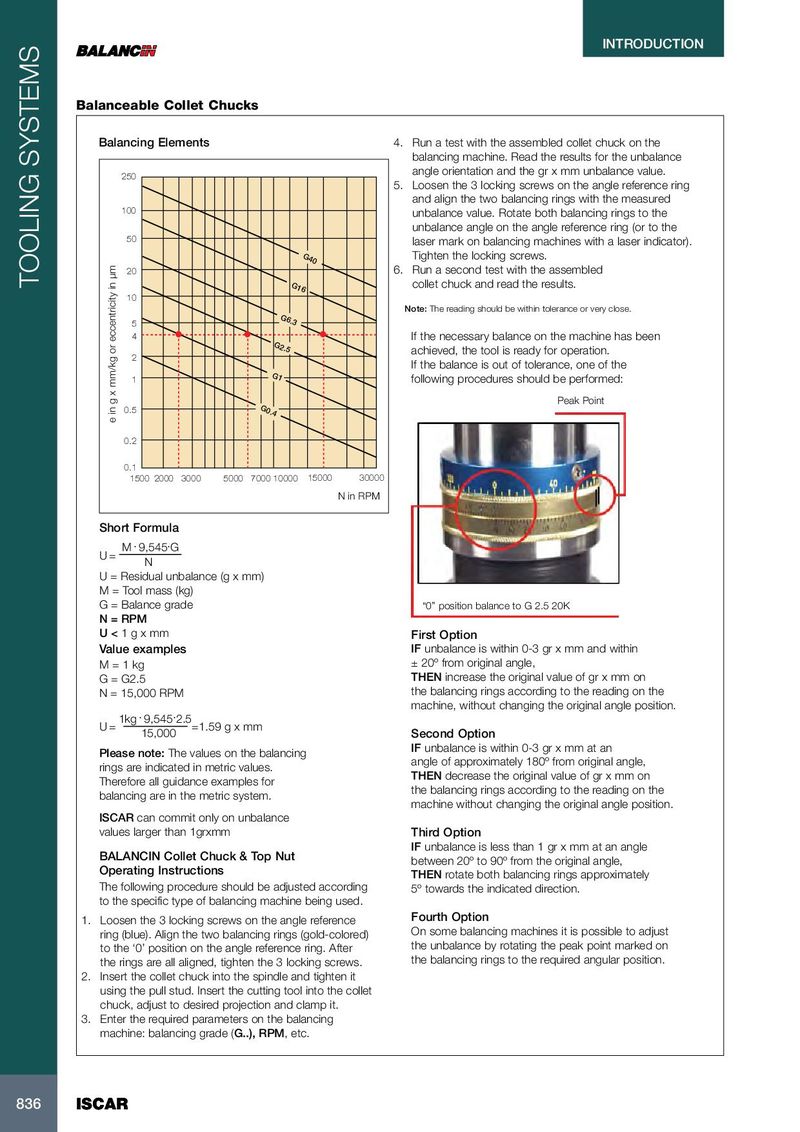
INTRODUCTION Balanceable Collet Chucks Balancing Elements 4. Run a test with the assembled collet chuck on the balancing machine. Read the results for the unbalance angle orientation and the gr x mm unbalance value. 250 5. Loosen the 3 locking screws on the angle reference ring and align the two balancing rings with the measured 100 unbalance value. Rotate both balancing rings to the unbalance angle on the angle reference ring (or to the 50 laser mark on balancing machines with a laser indicator). G 4 0 Tighten the locking screws. 20 6. Run a second test with the assembled TOOLING SYSTEMS G 1 6 collet chuck and read the results. 10 Note: The reading should be within tolerance or very close. G 6.3 5 4 If the necessary balance on the machine has been G2 .5 achieved, the tool is ready for operation. 2 If the balance is out of tolerance, one of the G1 1 following procedures should be performed: Peak Point 0.5 G0 .4 e in g x mm/kg or eccentricity in µm 0.2 0.1 1500 2000 3000 5000 7000 10000 15000 30000 N in RPM Short Formula . . M 9,545 G U = N U = Residual unbalance (g x mm) M = Tool mass (kg) G = Balance grade “0” position balance to G 2.5 20K N = RPM U < 1 g x mm First Option Value examples IF unbalance is within 0-3 gr x mm and within M = 1 kg ± 20º from original angle, G = G2.5 THEN increase the original value of gr x mm on N = 15,000 RPM the balancing rings according to the reading on the machine, without changing the original angle position. . . 1kg 9,545 2.5 U = =1.59 g x mm 15,000 Second Option IF unbalance is within 0-3 gr x mm at an Please note: The values on the balancing angle of approximately 180º from original angle, rings are indicated in metric values. THEN decrease the original value of gr x mm on Therefore all guidance examples for the balancing rings according to the reading on the balancing are in the metric system. machine without changing the original angle position. ISCAR can commit only on unbalance values larger than 1grxmm Third Option IF unbalance is less than 1 gr x mm at an angle BALANCIN Collet Chuck & Top Nut between 20º to 90º from the original angle, Operating Instructions THEN rotate both balancing rings approximately The following procedure should be adjusted according 5º towards the indicated direction. to the specific type of balancing machine being used. 1. Loosen the 3 locking screws on the angle reference Fourth Option ring (blue). Align the two balancing rings (gold-colored) On some balancing machines it is possible to adjust to the ‘0’ position on the angle reference ring. After the unbalance by rotating the peak point marked on the rings are all aligned, tighten the 3 locking screws. the balancing rings to the required angular position. 2. Insert the collet chuck into the spindle and tighten it using the pull stud. Insert the cutting tool into the collet chuck, adjust to desired projection and clamp it. 3. Enter the required parameters on the balancing machine: balancing grade (G..), RPM, etc. 836 836 ISCAR ISCAR