Каталог Iscar вращающийся инструмент 2017 - страница 535
Навигация
 Каталог Iscar токарные пластины ISO 2022
 Каталог Iscar инструмент для фрезерования
 Каталог Iscar решения для глубокого сверления
 Каталог Iscar полирующие фрезы
 Каталог Iscar новые продукты 2018
 Каталог Iscar концевые фрезы со сменными пластинами 2022
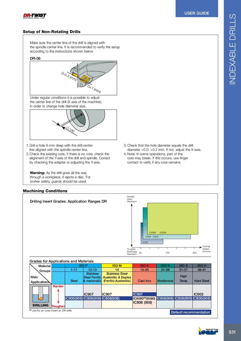
USER GUIDE Setup of Non-Rotating Drills Make sure the center line of the drill is aligned with the spindle center line. It is recommended to verify the setup according to the instructions shown below. DR-06 D-0.3 (mm) INDEXABLE DRILLS D+1 (mm) Under regular conditions it is possible to adjust the center line of the drill (X axis of the machine), in order to change hole diameter size. CORE 1. Drill a hole 6 mm deep with the drill center 3. Check that the hole diameter equals the drill line aligned with the spindle center line. diameter +0.0- +0.2 mm. If not, adjust the X-axis. 2. Check the existing core. If there is no core, check the 4. Note: In some operations, part of the alignment of the Y-axis of the drill and spindle. Correct core may break. If this occurs, use finger by checking the adapter or adjusting the Y-axis. contact to verify if any core remains. Warning: As the drill goes all the way through a workpiece, it ejects a disc. For worker safety, guards should be used. Machining Conditions Harder, Wear Drilling Insert Grades: Application Ranges DR Resistant IC9080 IC8080 IC808 IC908 IC328 Cutting Tougher, Speed Breakage (m/mm) 50 100 220 Resistant Grades for Applications and Materials Material ISO P ISO M ISO K ISO N ISO S ISO H 1-11 12-13 14 15-20 21-28 31-37 38-41 Groups Stainless Stainless Steel Main Steel Ferritic Austenitic & Duplex High Applications Steel & martensitic (Ferritic-Austenitic) Cast Iron Nonferrous Temp Hard Steel Harder IC907 IC907 IC907 IC903 IC808(908) IC808(908) IC808(908) IC8080 (1) (9080) IC808(908) IC808(908) IC808(908) IC808 (908) DRILLING Tougher (¹) Use for an outer insert on DR drills Default recommendation 531 531