Каталог Iscar вращающийся инструмент 2017 - страница 534
Навигация
 Каталог Iscar токарные пластины ISO 2022
 Каталог Iscar инструмент для фрезерования
 Каталог Iscar решения для глубокого сверления
 Каталог Iscar полирующие фрезы
 Каталог Iscar новые продукты 2018
 Каталог Iscar концевые фрезы со сменными пластинами 2022
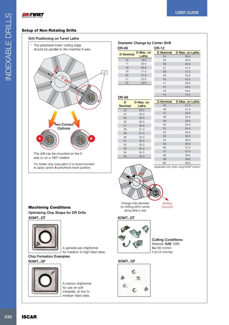
USER GUIDE Setup of Non-Rotating Drills Drill Positioning on Turret Lathe Diameter Change by Center Shift * The peripheral insert cutting edge should be parallel to the machine X-axis. DR-06 DR-12 D Max. on D Nominal D Max. on Lathe D Nominal Lathe 34 39.5 16 19.5 35 40.0 17 20.0 36 40.5 18 20.5 37 41.0 19 21.0 38 41.5 Y axis 20 21.5 39 42.0 X axis INDEXABLE DRILLS 21 22.0 40 42.5 22 23.0 41 43.0 42 43.5 43 44.0 44 44.5 DR-09 D D Max. on D Nominal D Max. on Lathe Nominal Lathe 45 51.0 23 28.5 46 51.5 24 29.0 47 52.0 25 29.5 48 52.5 26 30.0 49 53.0 Two Correct 27 30.5 50 54.0 Options 28 31.0 51 54.5 29 31.5 52 55.0 30 32.0 53 55.5 A B 31 32.5 54 56.0 32 33.3 55 56.5 33 34.0 56 57.0 34 34.5 57 57.5 The drill can be mounted on the X 35 35.0 58 58.0 axis or on a 180º rotation 59 59.0 60 60.0 For better chip evacuation it is recommended to apply option A peripheral insert position. Applicable only when using SOMT inserts Y axis X axis Change hole diameter Shifting Machining Conditions by shifting drill’s center Direction along lathe x-axis Optimizing Chip Shape for DR Drills SOMT...DT SOMT...DT Cutting Conditions: Material: SAE 1060 A general-use chipformer V=120 m/min for medium to high feed rates. f=0.14 mm/rev Chip Formation Examples SOMT...GF SOMT...GF A narrow chipformer for use on soft materials, at low to medium feed rates. 530 530 ISCAR ISCAR