Каталог Iscar вращающийся инструмент 2017 - страница 328
Навигация
 Каталог Iscar токарные пластины ISO 2022
 Каталог Iscar инструмент для фрезерования
 Каталог Iscar решения для глубокого сверления
 Каталог Iscar полирующие фрезы
 Каталог Iscar новые продукты 2018
 Каталог Iscar концевые фрезы со сменными пластинами 2022
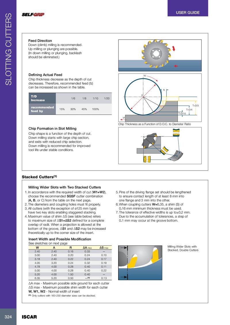
USER GUIDE Feed Direction Down (climb) milling is recommended. Up milling or plunging are possible. (In down milling or plunging, backlash should be eliminated.) Defining Actual Feed Vc Chip thickness decrease as the depth of cut SLOTTING CUTTERS decreases. Therefore, recommended feed (fz) can be increased as shown in the table. fz D T/D 1/6 1/8 1/10 1/20 Increase T=D/3 recommended 15% 30% 45% 100% T=D/4 feed by T=D/10 Vf Chip Thickness as a Function of D.O.C. to Diameter Ratio Chip Formation in Slot Milling Chip shape is a function of the depth of cut. Down milling starts with large chip section, and exits with reduced chip selection. Down milling is recommended for improved tool life under stable conditions. (1) Stacked Cutters Milling Wider Slots with Two Stacked Cutters 1. In accordance with the required width of cut (W1+W2), 5. Pins of the driving flange set should be lengthened choose the recommended SGSF cutter combination to ensure contact length of at least 8 mm into (A, B, or C) from the table on the next page. one flange and 3 mm into the other. 2. The diameters and coupling holes must fit properly. 6. When coupling cutters W=6.35, a shim (S) of 3. All cutters (with the exception of ø125 mm type) 0.16 mm minimum thickness must be used. have two key slots enabling staggered stacking. 7. The tolerance of effective widths is up to±0.2 mm. 4. Maximum value of shim ∆S (see table below) refers Due to the accumulation of tolerances, a step of to maximum size of ∆S1+∆S2 defined for a complete 0.1 mm may occur at the groove bottom. overlap of radii. When a projection is allowed at the bottom of the groove, ∆S1 and ∆S2 may be increased theoretically up to the corner size of the insert. Insert Width and Possible Modification See sketches on next page W A R ∆A max ∆S max Milling Wider Slots with Stacked, Double Cutters 2.40 2.40 0.16 0.33 — 3.00 2.40 0.20 0.24 0.10 3.18 2.40 0.22 0.24 0.17 4.05 3.20 0.24 0.32 0.19 4.78 4.00 0.28 0.40 0.11 5.00 4.00 0.28 0.40 0.22 5.20 4.00 1.50 0.40 — 6.35 5.20 0.50 — (1) 0.13 ∆A max - Maximum possible side ground for each cutter ∆S max - Maximum possible shim width for each cutter W, W1, W2 - Normal width of insert (1) Only cutters with 160-250 diameter sizes can be stacked. 324 324 ISCAR ISCAR