Каталог Iscar вращающийся инструмент 2017 - страница 325
Навигация
 Каталог Iscar токарные пластины ISO 2022
 Каталог Iscar инструмент для фрезерования
 Каталог Iscar решения для глубокого сверления
 Каталог Iscar полирующие фрезы
 Каталог Iscar новые продукты 2018
 Каталог Iscar концевые фрезы со сменными пластинами 2022
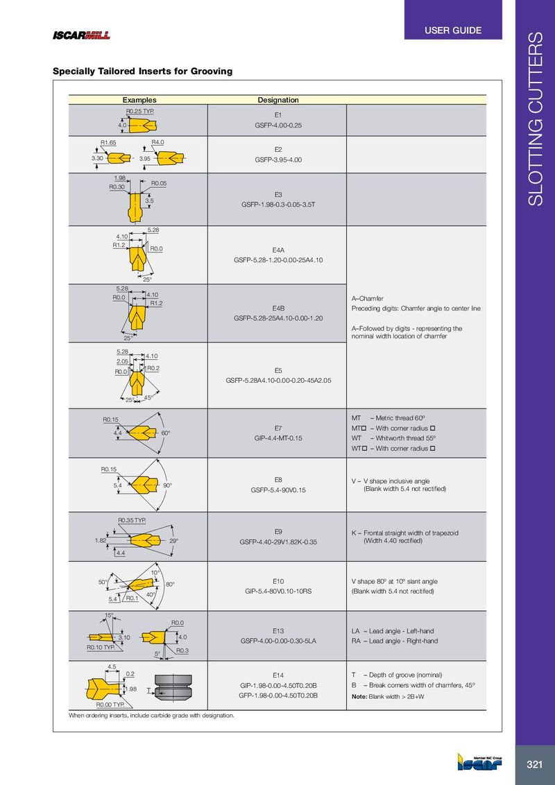
USER GUIDE Specially Tailored Inserts for Grooving Examples Designation R0.25 TYP. E1 4.0 GSFP-4.00-0.25 R1.65 R4.0 E2 3.30 3.95 GSFP-3.95-4.00 1.98 R0.05 R0.30 E3 3.5 GSFP-1.98-0.3-0.05-3.5T SLOTTING CUTTERS 5.28 4.10 R1.2 R0.0 E4A GSFP-5.28-1.20-0.00-25A4.10 25° 5.28 R0.0 4.10 A–Chamfer R1.2 E4B Preceding digits: Chamfer angle to center line GSFP-5.28-25A4.10-0.00-1.20 A–Followed by digits - representing the 25° nominal width location of chamfer 5.28 4.10 2.05 R0.2 R0.0 E5 GSFP-5.28A4.10-0.00-0.20-45A2.05 25° 45° R0.15 MT – Metric thread 60º E7 MTo – With corner radius o 4.4 60° GIP-4.4-MT-0.15 WT – Whitworth thread 55º WTo – With corner radius o R0.15 E8 V – V shape inclusive angle 5.4 90° GSFP-5.4-90V0.15 (Blank width 5.4 not rectified) R0.35 TYP. E9 K – Frontal straight width of trapezoid 1.82 29° GSFP-4.40-29V1.82K-0.35 (Width 4.40 rectified) 4.4 10° 50° E10 V shape 80º at 10º slant angle 80° GIP-5.4-80V0.10-10RS (Blank width 5.4 not recitifed) 40° 5.4 R0.1 15° R0.0 E13 LA – Lead angle - Left-hand 3.10 4.0 GSFP-4.00-0.00-0.30-5LA RA – Lead angle - Right-hand R0.10 TYP. R0.3 5° 4.5 0.2 E14 T – Depth of groove (nominal) GIP-1.98-0.00-4.50T0.20B B – Break corners width of chamfers, 45º 1.98 T GFP-1.98-0.00-4.50T0.20B Note: Blank width > 2B+W R0.00 TYP. When ordering inserts, include carbide grade with designation. 321 321