Каталог Iscar вращающийся инструмент 2017 - страница 318
Навигация
 Каталог Iscar токарные пластины ISO 2022
 Каталог Iscar инструмент для фрезерования
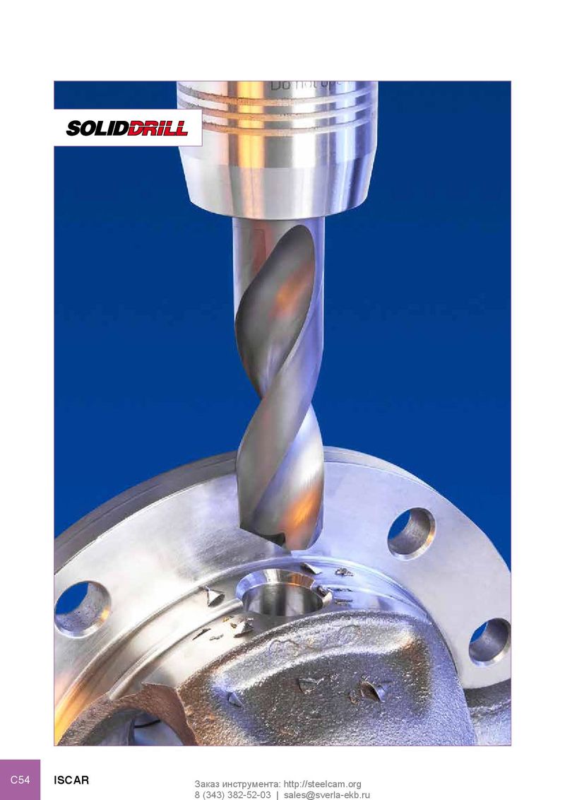 Каталог Iscar решения для глубокого сверления
 Каталог Iscar полирующие фрезы
 Каталог Iscar новые продукты 2018
 Каталог Iscar концевые фрезы со сменными пластинами 2022
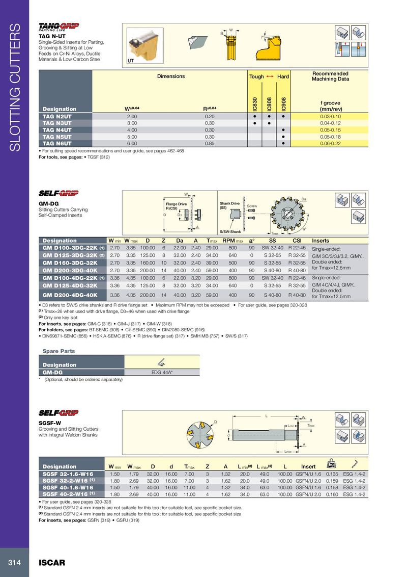
W R TAG N-UT 7° Single-Sided Inserts for Parting, Grooving & Slitting at Low Feeds on Cr-Ni Alloys, Ductile Materials & Low Carbon Steel Recommended Dimensions Tough 1 Hard Machining Data f groove Designation W ±0.04 R ±0.04 IC830 IC808 IC908 (mm/rev) TAG N2UT 2.00 0.20 • • • 0.03-0.10 TAG N3UT 3.00 0.30 • • 0.04-0.12 TAG N4UT 4.00 0.30 • 0.05-0.15 TAG N5UT 5.00 0.30 • 0.05-0.18 TAG N6UT 6.00 0.85 • 0.06-0.22 SLOTTING CUTTERS • For cutting speed recommendations and user guide, see pages 462-468 For tools, see pages: • TGSF (312) W Da GM-DG Flange Drive Shank Drive Slitting Cutters Carrying R (CSI) (SS) Screw Self-Clamped Inserts D D3 A a° S/SW-Shank Tmax Designation W min W max D Z Da A T max RPM max a° SS CSI Inserts GM D100-3DG-22K (1) 2.70 3.35 100.00 6 22.00 2.40 29.00 800 90 SW 32-40 R 22-46 Single-ended: GM D125-3DG-32K (2) 2.70 3.35 125.00 8 32.00 2.40 34.00 640 0 S 32-55 R 32-55 GIM 3C/3/3J/3.2, GIMY.. GM D160-3DG-32K 2.70 3.35 160.00 10 32.00 2.40 39.00 500 90 S 32-55 R 32-55 Double ended: for Tmax=12.5mm GM D200-3DG-40K 2.70 3.35 200.00 14 40.00 2.40 59.00 400 90 S 40-80 R 40-80 GM D100-4DG-22K (1) 3.36 4.35 100.00 6 22.00 3.20 29.00 800 90 SW 32-40 R 22-46 Single-ended: GM D125-4DG-32K 3.36 4.35 125.00 8 32.00 3.20 34.00 640 0 S 32-55 R 32-55 GIM 4C/4/4J, GIMY.. Double ended: GM D200-4DG-40K 3.36 4.35 200.00 14 40.00 3.20 59.00 400 90 S 40-80 R 40-80 for Tmax=12.5mm • D3 refers to SW/S drive shanks and R drive flange set • Maximum RPM may not be exceeded • For user guide, see pages 320-328 (1) Tmax=26 when used with drive flange, D3=46 when used with drive flange (2) Only one key slot For inserts, see pages: GIM-C (318) • GIM-J (317) • GIM-W (318) For holders, see pages: BT-SEMC (908) • C#-SEMC (890) • DIN2080-SEMC (916) • DIN69871-SEMC (856) • HSK A-SEMC (876) • R (drive flange set) (317) • SMH MB (757) • SW/S (317) Spare Parts Designation GM-DG EDG 44A* * (Optional, should be ordered separately) L W SGSF-W D Lmin Tmax Grooving and Slitting Cutters with Integral Weldon Shanks d A Lmax kg Designation W min W max D d T max Z A L min (2) L max (2) L Insert SGSF 32-1.6-W16 1.50 1.79 32.00 16.00 7.00 3 1.32 20.0 49.0 100.00 GSFN/U 1.6 0.135 ESG 1.4-2 SGSF 32-2-W16 (1) 1.80 2.69 32.00 16.00 7.00 3 1.62 20.0 49.0 100.00 GSFN/U 2.0 0.159 ESG 1.4-2 SGSF 40-1.6-W16 1.50 1.79 40.00 16.00 11.00 4 1.32 34.0 63.0 100.00 GSFN/U 1.6 0.158 ESG 1.4-2 SGSF 40-2-W16 (1) 1.80 2.69 40.00 16.00 11.00 4 1.62 34.0 63.0 100.00 GSFN/U 2.0 0.160 ESG 1.4-2 • For user guide, see pages 320-328 (1) Standard GSFN 2.4 mm inserts are not suitable for this tool; for suitable tool, see specific pocket size. (2) Standard GSFN 2.4 mm inserts are not suitable for this tool; for suitable tool, see specific pocket size For inserts, see pages: GSFN (319) • GSFU (319) 314 ISCAR