Каталог Iscar вращающийся инструмент 2017 - страница 272
Навигация
 Каталог Iscar токарные пластины ISO 2022
 Каталог Iscar инструмент для фрезерования
 Каталог Iscar решения для глубокого сверления
 Каталог Iscar полирующие фрезы
 Каталог Iscar новые продукты 2018
 Каталог Iscar концевые фрезы со сменными пластинами 2022
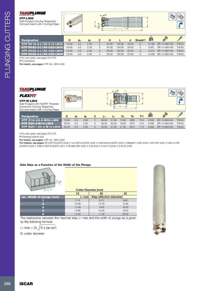
ap HTP-LN06 Side Plungers Carrying Tangentially D d Clamped Inserts with 4 Cutting Edges ae H L Designation D a e a p Z H L d Shank (1) kg HTP D016-2-L120-C16-LN06 16.00 4.5 2.50 2 32.00 120.00 16.00 C 0.166 SR 14-560-HG T-8/53 HTP D020-3-L150-C20-LN06 20.00 5.0 2.50 3 40.00 150.00 20.00 C 0.331 SR 14-560-HG T-8/53 HTP D025-3-L150-C25-LN06 25.00 5.0 2.50 3 50.00 150.00 25.00 C 0.513 SR 14-560-HG T-8/53 HTP D025-4-L130-C25-LN06 25.00 5.0 2.50 4 50.00 130.00 25.00 C 0.439 SR 14-560-HG T-8/53 • For user guide, see pages 272-276 (1) C-Cylindrical For inserts, see pages: HTP LN.. 0604 (456) PLUNGING CUTTERS ap T D Ts D3 HTP-M-LN06 ae Side Plungers with FLEXFIT Threaded Connection Carrying Tangentially L5 L6 Clamped Inserts with 4 Cutting Edges kg Designation D a e a p Z L 5 L 6 D 3 Ts T (1) HTP D16/.62-2-M08-LN06 15.95 4.5 2.50 2 30.00 47.50 13.00 M08 10.0 0.030 SR 14-560-HG T-8/53 HTP D20-3-M10-LN06 20.00 5.0 2.50 3 30.00 50.00 18.00 M10 15.0 0.058 SR 14-560-HG T-8/53 HTP D25/1.00-3-M12-LN06 25.20 5.0 2.50 3 35.00 57.00 21.00 M12 17.0 0.095 SR 14-560-HG T-8/53 • For user guide, see pages 272-276 (1) Clamping wrench size For inserts, see pages: HTP LN.. 0604 (456) For holders, see pages: BT-ODP (FLEXFIT) (248) • C#-ODP (FLEXFIT) (248) • CAB M-M (FLEXFIT) (245) • DIN69871-ODP (249) • ER-ODP (249) • HSK A-ODP (FLEXFIT) (250) • HSK E-ODP (FLEXFIT) (251) • RE MB-ODP (246) • S M (245) • S M-C-H (245) • S M-CF (246) Side Step as a Function of the Width of the Plunge ae L1 Cutter Diameter (mm) 16 20 25 ae - Width of plunge (mm) L1 max - Step (effective diameter) 1 7.75 8.72 9.80 2 10.58 12.00 13.56 3 12.49 1428 16.25 4 13.86 16.00 18.33 5 14.83 17.32 20.00 The relationship between the maximal step L1 max and the width of plunge ae is given by the following formula: L1 max = 2x D x (ae-ae 2 ) D: cutter diameter 268 ISCAR