Каталог Iscar токарный инструмент 2017 - страница 514
Навигация
 Каталог Iscar резьбонарезные фрезы
 Каталог Iscar инструмент для обработки алюминиевых колёс
 Каталог Iscar державки и пластины для нарезания резьбы 2022
 Каталог Iscar расточные системы 2022
 Каталог Iscar высокоточные развертки и метчики 2022
 Каталог Iscar вращающийся инструмент 2017
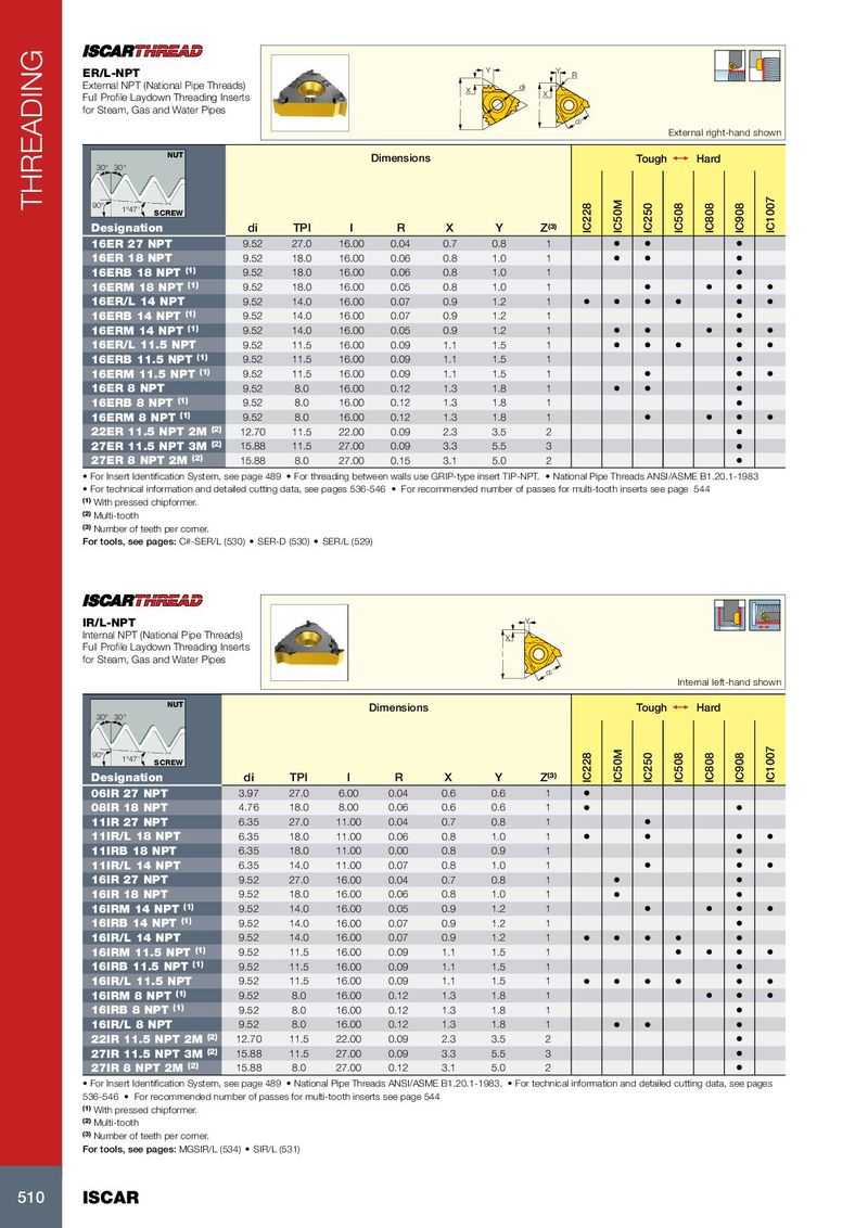
Y ER/L-NPT Y R External NPT (National Pipe Threads) X di X Full Profile Laydown Threading Inserts l l for Steam, Gas and Water Pipes di External right-hand shown NUT Dimensions Tough 1 Hard 30° 30° THREADING 90° 1°47' SCREW Designation di TPI l R X Y Z (3) IC228 IC50M IC250 IC508 IC808 IC908 IC1007 16ER 27 NPT 9.52 27.0 16.00 0.04 0.7 0.8 1 • • • 16ER 18 NPT 9.52 18.0 16.00 0.06 0.8 1.0 1 • • • 16ERB 18 NPT (1) 9.52 18.0 16.00 0.06 0.8 1.0 1 • 16ERM 18 NPT (1) 9.52 18.0 16.00 0.05 0.8 1.0 1 • • • • 16ER/L 14 NPT 9.52 14.0 16.00 0.07 0.9 1.2 1 • • • • • • 16ERB 14 NPT (1) 9.52 14.0 16.00 0.07 0.9 1.2 1 • 16ERM 14 NPT (1) 9.52 14.0 16.00 0.05 0.9 1.2 1 • • • • • 16ER/L 11.5 NPT 9.52 11.5 16.00 0.09 1.1 1.5 1 • • • • • 16ERB 11.5 NPT (1) 9.52 11.5 16.00 0.09 1.1 1.5 1 • 16ERM 11.5 NPT (1) 9.52 11.5 16.00 0.09 1.1 1.5 1 • • • 16ER 8 NPT 9.52 8.0 16.00 0.12 1.3 1.8 1 • • • 16ERB 8 NPT (1) 9.52 8.0 16.00 0.12 1.3 1.8 1 • 16ERM 8 NPT (1) 9.52 8.0 16.00 0.12 1.3 1.8 1 • • • • 22ER 11.5 NPT 2M (2) 12.70 11.5 22.00 0.09 2.3 3.5 2 • 27ER 11.5 NPT 3M (2) 15.88 11.5 27.00 0.09 3.3 5.5 3 • 27ER 8 NPT 2M (2) 15.88 8.0 27.00 0.15 3.1 5.0 2 • • For Insert Identification System, see page 489 • For threading between walls use GRIP-type insert TIP-NPT. • National Pipe Threads ANSI/ASME B1.20.1-1983 • For technical information and detailed cutting data, see pages 536-546 • For recommended number of passes for multi-tooth inserts see page 544 (1) With pressed chipformer. (2) Multi-tooth (3) Number of teeth per corner. For tools, see pages: C#-SER/L (530) • SER-D (530) • SER/L (529) IR/L-NPT Y Internal NPT (National Pipe Threads) X Full Profile Laydown Threading Inserts l for Steam, Gas and Water Pipes di Internal left-hand shown NUT Dimensions Tough 1 Hard 30° 30° 90° 1°47' SCREW Designation di TPI l R X Y Z (3) IC228 IC50M IC250 IC508 IC808 IC908 IC1007 06IR 27 NPT 3.97 27.0 6.00 0.04 0.6 0.6 1 • 08IR 18 NPT 4.76 18.0 8.00 0.06 0.6 0.6 1 • • 11IR 27 NPT 6.35 27.0 11.00 0.04 0.7 0.8 1 • 11IR/L 18 NPT 6.35 18.0 11.00 0.06 0.8 1.0 1 • • • • 11IRB 18 NPT 6.35 18.0 11.00 0.00 0.8 0.9 1 • 11IR/L 14 NPT 6.35 14.0 11.00 0.07 0.8 1.0 1 • • • 16IR 27 NPT 9.52 27.0 16.00 0.04 0.7 0.8 1 • • 16IR 18 NPT 9.52 18.0 16.00 0.06 0.8 1.0 1 • • 16IRM 14 NPT (1) 9.52 14.0 16.00 0.05 0.9 1.2 1 • • • • 16IRB 14 NPT (1) 9.52 14.0 16.00 0.07 0.9 1.2 1 • 16IR/L 14 NPT 9.52 14.0 16.00 0.07 0.9 1.2 1 • • • • • 16IRM 11.5 NPT (1) 9.52 11.5 16.00 0.09 1.1 1.5 1 • • • • 16IRB 11.5 NPT (1) 9.52 11.5 16.00 0.09 1.1 1.5 1 • 16IR/L 11.5 NPT 9.52 11.5 16.00 0.09 1.1 1.5 1 • • • • • • 16IRM 8 NPT (1) 9.52 8.0 16.00 0.12 1.3 1.8 1 • • • 16IRB 8 NPT (1) 9.52 8.0 16.00 0.12 1.3 1.8 1 • 16IR/L 8 NPT 9.52 8.0 16.00 0.12 1.3 1.8 1 • • • 22IR 11.5 NPT 2M (2) 12.70 11.5 22.00 0.09 2.3 3.5 2 • 27IR 11.5 NPT 3M (2) 15.88 11.5 27.00 0.09 3.3 5.5 3 • 27IR 8 NPT 2M (2) 15.88 8.0 27.00 0.12 3.1 5.0 2 • • For Insert Identification System, see page 489 • National Pipe Threads ANSI/ASME B1.20.1-1983. • For technical information and detailed cutting data, see pages 536-546 • For recommended number of passes for multi-tooth inserts see page 544 (1) With pressed chipformer. (2) Multi-tooth (3) Number of teeth per corner. For tools, see pages: MGSIR/L (534) • SIR/L (531) 510 ISCAR