Каталог Iscar токарный инструмент 2017 - страница 495
Навигация
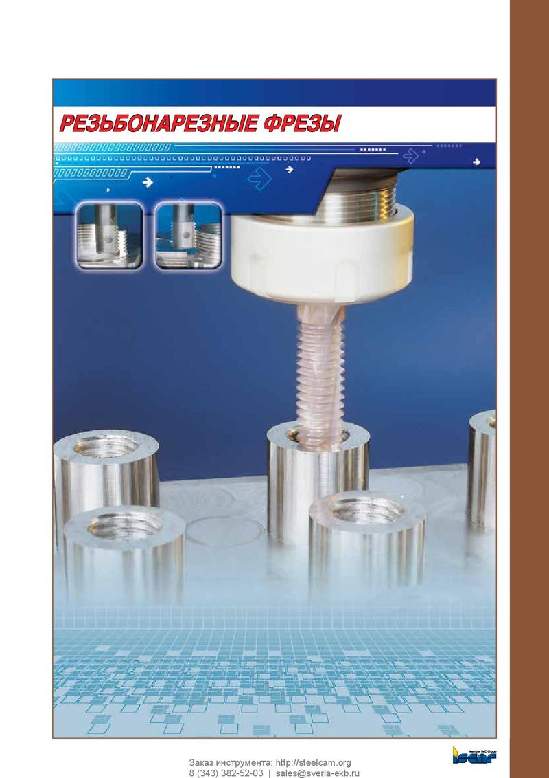 Каталог Iscar резьбонарезные фрезы
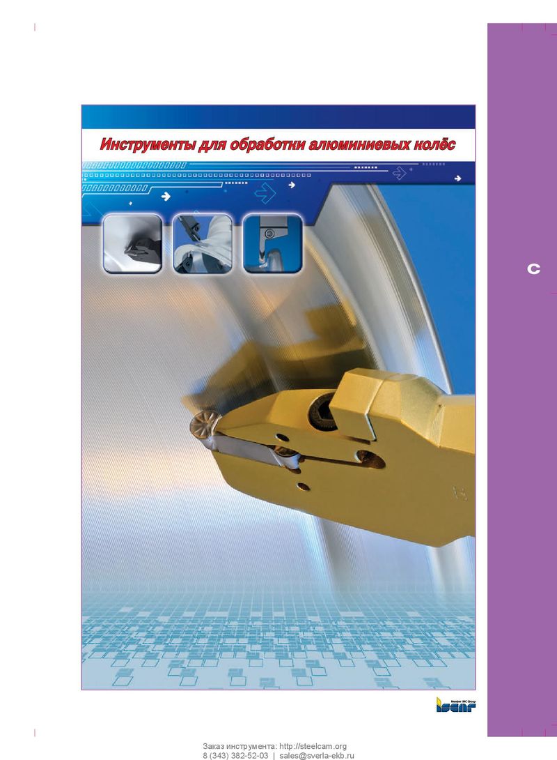 Каталог Iscar инструмент для обработки алюминиевых колёс
 Каталог Iscar державки и пластины для нарезания резьбы 2022
 Каталог Iscar расточные системы 2022
 Каталог Iscar высокоточные развертки и метчики 2022
 Токарные инструменты Iscar (часть 2) 2026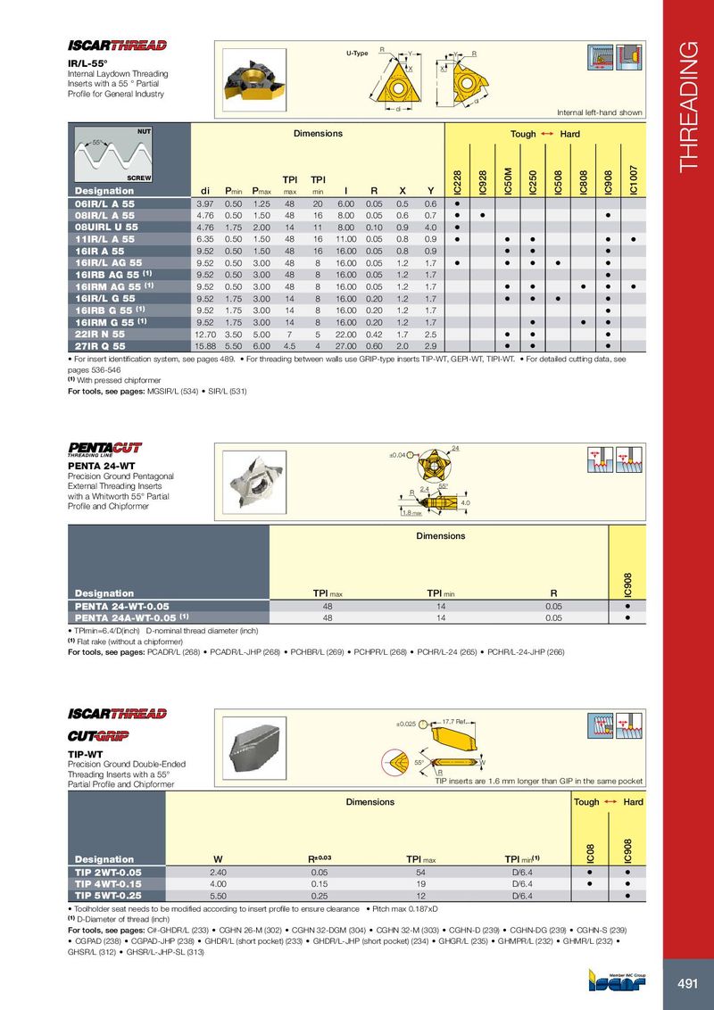
THREADING
R
U-Type Y Y R
IR/L-55° X X
Internal Laydown Threading l
Inserts with a 55 ° Partial l
Profile for General Industry
di
di
Internal left-hand shown
NUT
Dimensions Tough 1 Hard
55°
IC1007
IC50M
IC228
IC928
IC250
IC508
IC808
IC908
SCREW TPI TPI
Designation di Pmin Pmax max min l R X Y
06IR/L A 55 3.97 0.50 1.25 48 20 6.00 0.05 0.5 0.6 •
08IR/L A 55 4.76 0.50 1.50 48 16 8.00 0.05 0.6 0.7 • • •
08UIRL U 55 4.76 1.75 2.00 14 11 8.00 0.10 0.9 4.0 •
11IR/L A 55 6.35 0.50 1.50 48 16 11.00 0.05 0.8 0.9 • • • • •
16IR A 55 9.52 0.50 1.50 48 16 16.00 0.05 0.8 0.9 • • •
16IR/L AG 55 9.52 0.50 3.00 48 8 16.00 0.05 1.2 1.7 • • • • •
16IRB AG 55 (1) 9.52 0.50 3.00 48 8 16.00 0.05 1.2 1.7 •
16IRM AG 55 (1) 9.52 0.50 3.00 48 8 16.00 0.05 1.2 1.7 • • • • •
16IR/L G 55 9.52 1.75 3.00 14 8 16.00 0.20 1.2 1.7 • • • •
16IRB G 55 (1) 9.52 1.75 3.00 14 8 16.00 0.20 1.2 1.7 •
16IRM G 55 (1) 9.52 1.75 3.00 14 8 16.00 0.20 1.2 1.7 • • •
22IR N 55 12.70 3.50 5.00 7 5 22.00 0.42 1.7 2.5 • • •
27IR Q 55 15.88 5.50 6.00 4.5 4 27.00 0.60 2.0 2.9 • • •
• For insert identification system, see pages 489. • For threading between walls use GRIP-type inserts TIP-WT, GEPI-WT, TIPI-WT. • For detailed cutting data, see
pages 536-546
(1) With pressed chipformer
For tools, see pages: MGSIR/L (534) • SIR/L (531)
24
±0.04
PENTA 24-WT
Precision Ground Pentagonal
External Threading Inserts 2.4 55°
R
with a Whitworth 55° Partial
4.0
Profile and Chipformer
1.8 max
Dimensions
IC908
Designation TPI max TPI min R
PENTA 24-WT-0.05 48 14 0.05 •
PENTA 24A-WT-0.05 (1) 48 14 0.05 •
• TPImin=6.4/D(inch) D-nominal thread diameter (inch)
(1) Flat rake (without a chipformer)
For tools, see pages: PCADR/L (268) • PCADR/L-JHP (268) • PCHBR/L (269) • PCHPR/L (268) • PCHR/L-24 (265) • PCHR/L-24-JHP (266)
±0.025 17.7 Ref.
TIP-WT
Precision Ground Double-Ended 55° W
Threading Inserts with a 55° R
Partial Profile and Chipformer TIP inserts are 1.6 mm longer than GIP in the same pocket
Dimensions Tough 1 Hard
IC908
IC08
Designation W R±0.03 TPI max TPI min(1)
TIP 2WT-0.05 2.40 0.05 54 D/6.4 • •
TIP 4WT-0.15 4.00 0.15 19 D/6.4 • •
TIP 5WT-0.25 5.50 0.25 12 D/6.4 •
• Toolholder seat needs to be modified according to insert profile to ensure clearance • Pitch max 0.187xD
(1) D-Diameter of thread (inch)
For tools, see pages: C#-GHDR/L (233) • CGHN 26-M (302) • CGHN 32-DGM (304) • CGHN 32-M (303) • CGHN-D (239) • CGHN-DG (239) • CGHN-S (239)
• CGPAD (238) • CGPAD-JHP (238) • GHDR/L (short pocket) (233) • GHDR/L-JHP (short pocket) (234) • GHGR/L (235) • GHMPR/L (232) • GHMR/L (232) •
GHSR/L (312) • GHSR/L-JHP-SL (313)
491
R
U-Type Y Y R
IR/L-55° X X
Internal Laydown Threading l
Inserts with a 55 ° Partial l
Profile for General Industry
di
di
Internal left-hand shown
NUT
Dimensions Tough 1 Hard
55°
IC1007
IC50M
IC228
IC928
IC250
IC508
IC808
IC908
SCREW TPI TPI
Designation di Pmin Pmax max min l R X Y
06IR/L A 55 3.97 0.50 1.25 48 20 6.00 0.05 0.5 0.6 •
08IR/L A 55 4.76 0.50 1.50 48 16 8.00 0.05 0.6 0.7 • • •
08UIRL U 55 4.76 1.75 2.00 14 11 8.00 0.10 0.9 4.0 •
11IR/L A 55 6.35 0.50 1.50 48 16 11.00 0.05 0.8 0.9 • • • • •
16IR A 55 9.52 0.50 1.50 48 16 16.00 0.05 0.8 0.9 • • •
16IR/L AG 55 9.52 0.50 3.00 48 8 16.00 0.05 1.2 1.7 • • • • •
16IRB AG 55 (1) 9.52 0.50 3.00 48 8 16.00 0.05 1.2 1.7 •
16IRM AG 55 (1) 9.52 0.50 3.00 48 8 16.00 0.05 1.2 1.7 • • • • •
16IR/L G 55 9.52 1.75 3.00 14 8 16.00 0.20 1.2 1.7 • • • •
16IRB G 55 (1) 9.52 1.75 3.00 14 8 16.00 0.20 1.2 1.7 •
16IRM G 55 (1) 9.52 1.75 3.00 14 8 16.00 0.20 1.2 1.7 • • •
22IR N 55 12.70 3.50 5.00 7 5 22.00 0.42 1.7 2.5 • • •
27IR Q 55 15.88 5.50 6.00 4.5 4 27.00 0.60 2.0 2.9 • • •
• For insert identification system, see pages 489. • For threading between walls use GRIP-type inserts TIP-WT, GEPI-WT, TIPI-WT. • For detailed cutting data, see
pages 536-546
(1) With pressed chipformer
For tools, see pages: MGSIR/L (534) • SIR/L (531)
24
±0.04
PENTA 24-WT
Precision Ground Pentagonal
External Threading Inserts 2.4 55°
R
with a Whitworth 55° Partial
4.0
Profile and Chipformer
1.8 max
Dimensions
IC908
Designation TPI max TPI min R
PENTA 24-WT-0.05 48 14 0.05 •
PENTA 24A-WT-0.05 (1) 48 14 0.05 •
• TPImin=6.4/D(inch) D-nominal thread diameter (inch)
(1) Flat rake (without a chipformer)
For tools, see pages: PCADR/L (268) • PCADR/L-JHP (268) • PCHBR/L (269) • PCHPR/L (268) • PCHR/L-24 (265) • PCHR/L-24-JHP (266)
±0.025 17.7 Ref.
TIP-WT
Precision Ground Double-Ended 55° W
Threading Inserts with a 55° R
Partial Profile and Chipformer TIP inserts are 1.6 mm longer than GIP in the same pocket
Dimensions Tough 1 Hard
IC908
IC08
Designation W R±0.03 TPI max TPI min(1)
TIP 2WT-0.05 2.40 0.05 54 D/6.4 • •
TIP 4WT-0.15 4.00 0.15 19 D/6.4 • •
TIP 5WT-0.25 5.50 0.25 12 D/6.4 •
• Toolholder seat needs to be modified according to insert profile to ensure clearance • Pitch max 0.187xD
(1) D-Diameter of thread (inch)
For tools, see pages: C#-GHDR/L (233) • CGHN 26-M (302) • CGHN 32-DGM (304) • CGHN 32-M (303) • CGHN-D (239) • CGHN-DG (239) • CGHN-S (239)
• CGPAD (238) • CGPAD-JHP (238) • GHDR/L (short pocket) (233) • GHDR/L-JHP (short pocket) (234) • GHGR/L (235) • GHMPR/L (232) • GHMR/L (232) •
GHSR/L (312) • GHSR/L-JHP-SL (313)
491