Каталог Iscar токарный инструмент 2017 - страница 370
Навигация
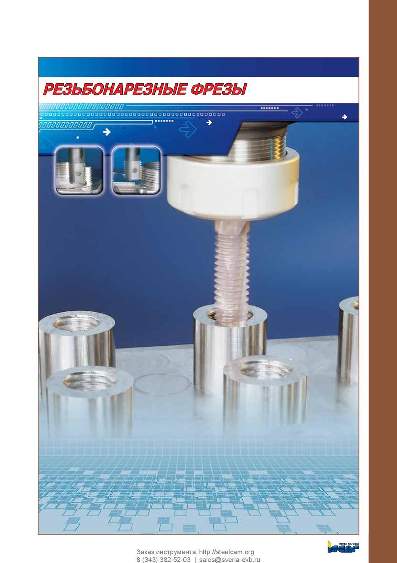 Каталог Iscar резьбонарезные фрезы
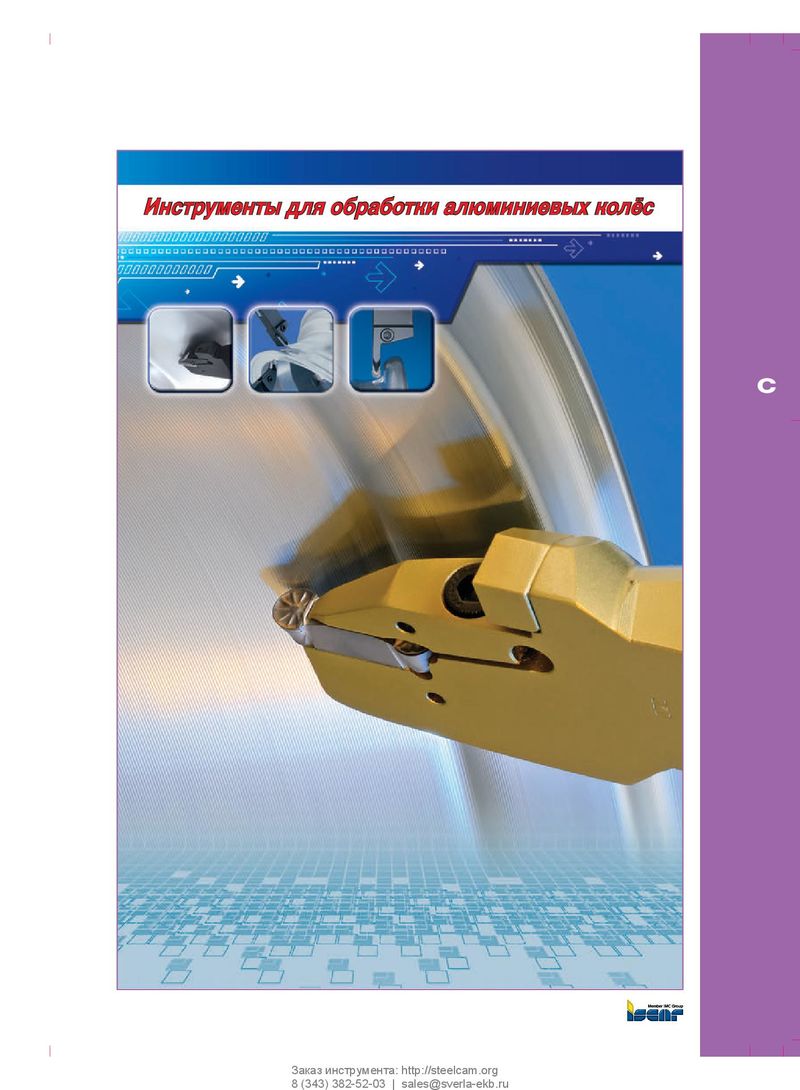 Каталог Iscar инструмент для обработки алюминиевых колёс
 Каталог Iscar державки и пластины для нарезания резьбы 2022
 Каталог Iscar расточные системы 2022
 Каталог Iscar высокоточные развертки и метчики 2022
 Токарные инструменты Iscar (часть 2) 2026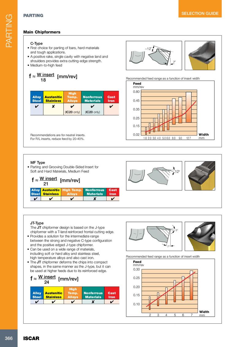
Main Chipformers
C-Type
- First choice for parting of bars, hard materials ~12˚ and tough applications.
- A positive rake, single cavity with negative land and shoulders provides extra cutting-edge strength. 7˚
- Medium-to-high feed f ≈ W insert [mm/rev]
18 Recommended feed range as a function of insert width Feed mm/rev High 0.80
| Alloy | Austenitic | Temp. | Nonferrous | Cast | ||
| Steel | Stainless | Alloys | Materials | Iron | 0.45 | |
| 0.35 | ||||||
| (IC20 only) | (IC20 only) | |||||
| 0.25 | ||||||
| 0.15 | ||||||
| Recommendations are for neutral inserts. | 0.02 | Width | ||||
| For R/L inserts, reduce feed by 20-40%. | 12.7 5.0 6.0 8.0 9.0 1.6 2.0 3.0 4.0 mm |
MF Type
- Parting and Grooving Double-Sided Insert for Soft and Hard Materials, Medium Feed 12° f ≈ W insert [mm/rev] 21
| Alloy Austenitic | High Temp. | Nonferrous | Cast | ||
| Steel | Stainless | Alloys | Materials | Iron |
JT-Type The JT chipformer design is based on the J-type chipformer with a T-land reinforced frontal cutting edge. 5°
- Provides a solution for the intermediate range between the strong and negative C-type configuration and the positive edged J-type chipformer.
7°
- Can be used on a wide range of materials, including soft or hard alloy and stainless steel, high temperature alloys and also cast iron. Recommended feed range as a function of insert width
- The JT chipformer deforms the chips into compact Feed shapes, in the same manner as the J-type, but it can mm/rev be used at higher feeds due to its reinforced edge. 0.30
| f ≈ W insert | [mm/rev] | 0.25 | |
| 24 | |||
| 0.20 | |||
| High |
| Alloy | Austenitic | Temp. | Nonferrous | Cast | ||
| 0.15 | ||||||
| Steel | Stainless | Alloys | Materials | Iron | ||
| 0.10 | ||||||
| Width |
2 3 4 5 6 7 mm