Каталог Iscar токарный инструмент 2017 - страница 361
Навигация
 Каталог Iscar резьбонарезные фрезы
 Каталог Iscar инструмент для обработки алюминиевых колёс
 Каталог Iscar державки и пластины для нарезания резьбы 2022
 Каталог Iscar расточные системы 2022
 Каталог Iscar высокоточные развертки и метчики 2022
 Каталог Iscar вращающийся инструмент 2017
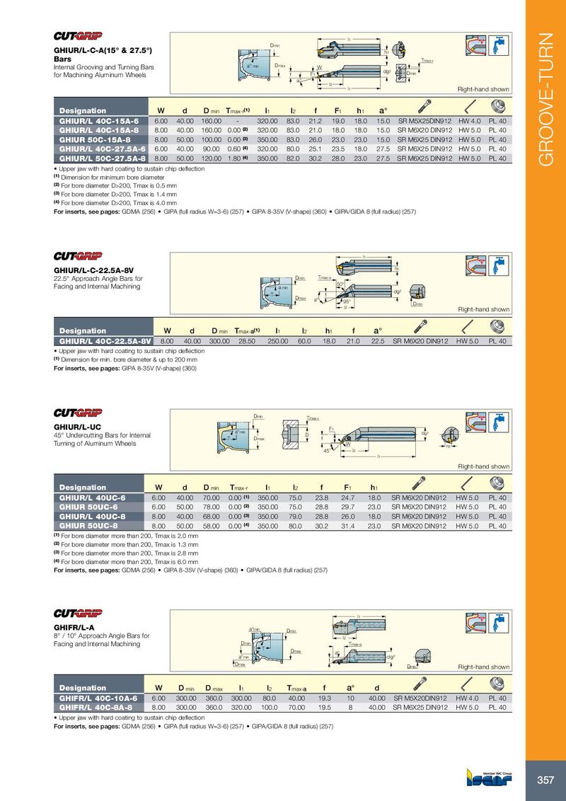
l 1 Dmin GHIUR/L-C-A(15° & 27.5°) h 1 Bars Tmax-r Internal Grooving and Turning Bars a° min Dmax W dg 7 for Machining Aluminum Wheels f F 1 Dmin a° l 2 l 1 Right-hand shown Designation W d D min T max-r (1) l 1 l 2 f F 1 h 1 a° GHIUR/L 40C-15A-6 6.00 40.00 160.00 - 320.00 83.0 21.2 19.0 18.0 15.0 SR M5X25DIN912 HW 4.0 PL 40 GHIUR/L 40C-15A-8 8.00 40.00 160.00 0.00 (2) 320.00 83.0 21.0 18.0 18.0 15.0 SR M6X20 DIN912 HW 5.0 PL 40 GHIUR 50C-15A-8 8.00 50.00 100.00 0.00 (3) 350.00 83.0 26.0 23.0 23.0 15.0 SR M6X25 DIN912 HW 5.0 PL 40 GHIUR/L 40C-27.5A-6 6.00 40.00 90.00 0.60 (4) 320.00 80.0 25.1 23.5 18.0 27.5 SR M6X25 DIN912 HW 5.0 PL 40 GHIUR/L 50C-27.5A-8 8.00 50.00 120.00 1.80 (4) 350.00 82.0 30.2 28.0 23.0 27.5 SR M6X25 DIN912 HW 5.0 PL 40 GROOVE-TURN • Upper jaw with hard coating to sustain chip deflection (1) Dimension for minimum bore diameter (2) For bore diameter D>200, Tmax is 0.5 mm (3) For bore diameter D>200, Tmax is 1.4 mm (4) For bore diameter D>200, Tmax is 4.0 mm For inserts, see pages: GDMA (256) • GIPA (full radius W=3-6) (257) • GIPA 8-35V (V-shape) (360) • GIPA/GIDA 8 (full radius) (257) l 1 h 1 GHIUR/L-C-22.5A-8V 22.5° Approach Angle Bars for Dmin Tmax-a Facing and Internal Machining 50° a min dg 7 T f Dmax a° 95° Dmin l 2 Right-hand shown Designation W d D min T max- a (1) l 1 l 2 h 1 f a° GHIUR/L 40C-22.5A-8V 8.00 40.00 300.00 28.50 250.00 60.0 18.0 21.0 22.5 SR M6X20 DIN912 HW 5.0 PL 40 • Upper jaw with hard coating to sustain chip deflection (1) Dimension for min. bore diameter & up to 200 mm For inserts, see pages: GIPA 8-35V (V-shape) (360) Dmin Tmax-r GHIUR/L-UC a°min F1 45° Undercutting Bars for Internal D dg7 T Dmax f Turning of Aluminum Wheels W h1 45˚ l2 l1 Right-hand shown Designation W d D min T max-r l 1 l 2 f F 1 h 1 GHIUR/L 40UC-6 6.00 40.00 70.00 0.00 (1) 350.00 75.0 23.8 24.7 18.0 SR M6X20 DIN912 HW 5.0 PL 40 GHIUR 50UC-6 6.00 50.00 78.00 0.00 (2) 350.00 75.0 28.8 29.7 23.0 SR M6X20 DIN912 HW 5.0 PL 40 GHIUR/L 40UC-8 8.00 40.00 68.00 0.00 (3) 350.00 79.0 28.8 26.0 18.0 SR M6X20 DIN912 HW 5.0 PL 40 GHIUR 50UC-8 8.00 50.00 58.00 0.00 (4) 350.00 80.0 30.2 31.4 23.0 SR M6X20 DIN912 HW 5.0 PL 40 (1) For bore diameter more than 200, Tmax is 2.0 mm (2) For bore diameter more than 200, Tmax is 1.3 mm (3) For bore diameter more than 200, Tmax is 2.8 mm (4) For bore diameter more than 200, Tmax is 6.0 mm For inserts, see pages: GDMA (256) • GIPA 8-35V (V-shape) (360) • GIPA/GIDA 8 (full radius) (257) l 1 GHIFR/L-A a°min Dmin 8° / 10° Approach Angle Bars for l 2 Facing and Internal Machining Dmin Tmax-a T Dmax a° a°min dg 7 f Dmax Dmin Right-hand shown Designation W D min D max l 1 l 2 T max- a f a° d GHIFR/L 40C-10A-6 6.00 300.00 360.0 300.00 80.0 40.00 19.3 10 40.00 SR M5X20DIN912 HW 4.0 PL 40 GHIFR/L 40C-8A-8 8.00 300.00 360.0 320.00 100.0 70.00 19.5 8 40.00 SR M6X25 DIN912 HW 5.0 PL 40 • Upper jaw with hard coating to sustain chip deflection For inserts, see pages: GDMA (256) • GIPA (full radius W=3-6) (257) • GIPA/GIDA 8 (full radius) (257) 357