Каталог Iscar токарный инструмент 2017 - страница 299
Навигация
 Каталог Iscar резьбонарезные фрезы
 Каталог Iscar инструмент для обработки алюминиевых колёс
 Каталог Iscar державки и пластины для нарезания резьбы 2022
 Каталог Iscar расточные системы 2022
 Каталог Iscar высокоточные развертки и метчики 2022
 Каталог Iscar вращающийся инструмент 2017
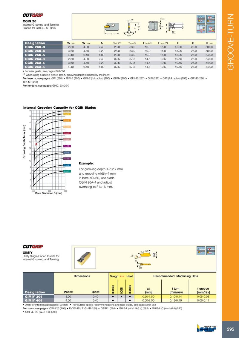
W Tmax-r CGIN 26 Internal Grooving and Turning B1 Dmin Blades for GHIC...-50 Bars h1 f F1 l1 A 150° Designation W min W max A f min (1) f max (1) F 1min (1) F 1max (1) l 1 B 1 D min CGIN 26K-3 2.80 4.00 2.40 28.0 33.0 10.0 15.0 45.00 26.0 50.00 CGIN 26K-4 3.60 4.50 3.20 28.0 33.0 10.0 15.0 45.00 26.0 50.00 CGIN 26K-5 4.40 6.40 4.00 28.0 33.0 10.0 15.0 45.00 26.0 54.00 CGIN 26A-3 2.80 4.00 2.40 32.5 37.5 14.5 19.5 49.50 26.0 54.00 CGIN 26A-4 3.60 4.50 3.20 32.5 37.5 14.5 19.5 49.50 26.0 54.00 CGIN 26A-5 4.40 6.40 4.00 32.5 37.5 14.5 19.5 49.50 26.0 54.00 GROOVE-TURN • For user guide, see pages 340-351 (1) When using a double-ended insert, grooving depth is limited by the insert. For inserts, see pages: GIFI (298) • GIFI-E (296) • GIFI-E (full radius) (296) • GIMIY (295) • GINI-E (297) • GIPI (297) • GIPI (full radius) (298) • GIPI-E (296) • TIPI-MT (299) For holders, see pages: GHIC-50 (294) Internal Grooving Capacity for CGIN Blades 18 F1=19.5 F1=19 17 F1=18 16 F1=17 15 F1=16 14 F1=15 13 F1=14 12 F1=13 11 Grooving Depth Tmax (mm) F1=12 10 Example: F1=11 9 For grooving depth T=12.7 mm F1=10 8 and grooving width=4 mm in bore øD=60, use blade 7 CGIN 26A-4 and adjust 6 overhang to F1=16 mm. 50 100 150 Bore Diameter D (mm) GIMIY 15.7 Ref. 5 Utility Single-Ended Inserts for ±0.1 Internal Grooving and Turning W R Dimensions Tough 1 Hard Recommended Machining Data a p f turn f groove Designation W ±0.02 R ±0.05 IC830 IC08 IC808 (mm) (mm/rev) (mm/rev) GIMIY 304 3.00 0.40 • • • 0.50-1.50 0.10-0.14 0.05-0.08 GIMIY 404 4.00 0.40 • • 0.50-2.00 0.13-0.19 0.06-0.11 • Dmin for internal applications=20 mm • For cutting speed recommendations and user guide, see pages 340-351 For tools, see pages: CGIN 26 (295) • E-GEHIR / E-GHIR (289) • GAIR/L (294) • GHIR/L (W=1.9-6.4) (293) • GHIR/L-C (W=4-6.4) (293) • GHIR/L-SC (W=2-4.8) (293) 295