Каталог Iscar токарный инструмент 2017 - страница 298
Навигация
 Каталог Iscar резьбонарезные фрезы
 Каталог Iscar инструмент для обработки алюминиевых колёс
 Каталог Iscar державки и пластины для нарезания резьбы 2022
 Каталог Iscar расточные системы 2022
 Каталог Iscar высокоточные развертки и метчики 2022
 Каталог Iscar вращающийся инструмент 2017
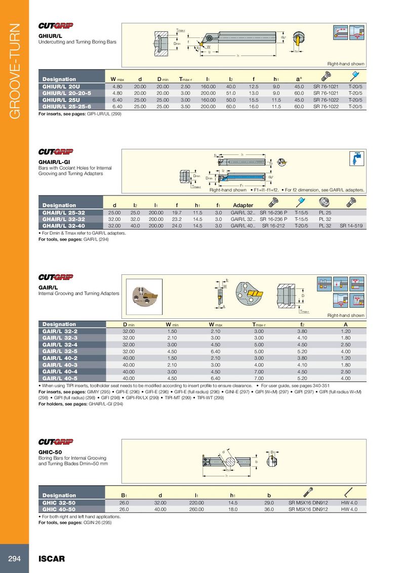
Tmax-r
GHIUR/L dg7
Undercutting and Turning Boring Bars Dmin f
a W
l2 h1
l1
Right-hand shown
Designation W max d D min T max-r l 1 l 2 f h 1 a°
GHIUR/L 20U 4.80 20.00 20.00 2.50 160.00 40.0 12.5 9.0 45.0 SR 76-1021 T-20/5
GHIUR/L 20-20-5 4.80 20.00 20.00 3.00 200.00 51.0 13.0 9.0 60.0 SR 76-1021 T-20/5
GHIUR/L 25U 6.40 25.00 25.00 3.00 160.00 50.0 15.5 11.5 45.0 SR 76-1022 T-20/5
GHIUR/L 25-25-6 6.40 25.00 25.00 3.50 200.00 60.0 16.0 11.5 60.0 SR 76-1022 T-20/5
For inserts, see pages: GIPI-UR/UL (299)
GROOVE-TURN
f1 l1
GHAIR/L-GI h1
Bars with Coolant Holes for Internal
l2
Grooving and Turning Adapters
Dmin
Dmin dg7
f
Tmax-r F1
Right-hand shown • F1=l1-f1+f2. • For f2 dimension, see GAIR/L adapters.
Designation d l 2 l 1 f h 1 f 1 Adapter
GHAIR/L 25-32 25.00 25.0 200.00 19.7 11.5 3.0 GAIR/L 32.. SR 16-236 P T-15/5 PL 25
GHAIR/L 32-32 32.00 32.0 200.00 23.2 14.5 3.0 GAIR/L 32.. SR 16-236 P T-15/5 PL 32
GHAIR/L 32-40 32.00 40.0 200.00 24.0 14.5 3.0 GAIR/L 40.. SR 16-212 T-20/5 PL 32 SR 14-519
• For Dmin & Tmax refer to GAIR/L adapters.
For tools, see pages: GAIR/L (294)
f2
GAIR/L W
Internal Grooving and Turning Adapters
D
A
Tmax-r
Right-hand shown
Designation D min W min W max T max-r f 2 A
GAIR/L 32-2 32.00 1.50 2.10 3.00 3.80 1.20
GAIR/L 32-3 32.00 2.10 3.00 3.00 4.10 1.80
GAIR/L 32-4 32.00 3.00 4.50 5.00 4.50 2.50
GAIR/L 32-5 32.00 4.50 6.40 5.00 5.20 4.00
GAIR/L 40-2 40.00 1.50 2.10 3.00 3.80 1.20
GAIR/L 40-3 40.00 2.10 3.00 4.00 4.10 1.80
GAIR/L 40-4 40.00 3.00 4.50 7.00 4.50 2.50
GAIR/L 40-5 40.00 4.50 6.40 7.00 5.20 4.00
• When using TIPI inserts, toolholder seat needs to be modified according to insert profile to ensure clearance. • For user guide, see pages 340-351
For inserts, see pages: GIMIY (295) • GIPI-E (296) • GIFI-E (296) • GIFI-E (full radius) (296) • GINI-E (297) • GIPI (W