Каталог Iscar токарный инструмент 2017 - страница 259
Навигация
 Каталог Iscar резьбонарезные фрезы
 Каталог Iscar инструмент для обработки алюминиевых колёс
 Каталог Iscar державки и пластины для нарезания резьбы 2022
 Каталог Iscar расточные системы 2022
 Каталог Iscar высокоточные развертки и метчики 2022
 Каталог Iscar вращающийся инструмент 2017
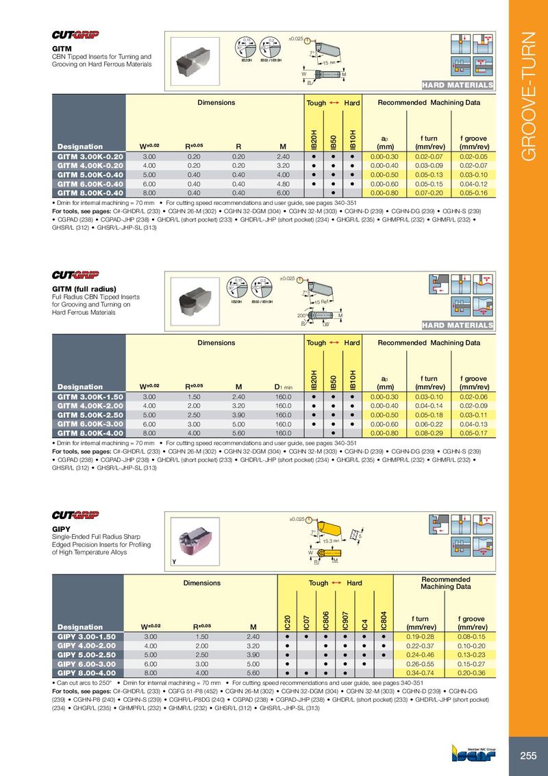
0.15 0.2 ±0.025 GITM 30° 20° 7° CBN Tipped Inserts for Turning and IB20H IB50 / IB10H Grooving on Hard Ferrous Materials 15 Ref. W M R HARD MATERIALS Dimensions Tough 1 Hard Recommended Machining Data a p f turn f groove Designation W ±0.02 R ±0.05 R M IB20H IB50 IB10H (mm) (mm/rev) (mm/rev) GITM 3.00K-0.20 3.00 0.20 0.20 2.40 • • • 0.00-0.30 0.02-0.07 0.02-0.05 GROOVE-TURN GITM 4.00K-0.20 4.00 0.20 0.20 3.20 • • • 0.00-0.40 0.03-0.09 0.02-0.07 GITM 5.00K-0.40 5.00 0.40 0.40 4.00 • • • 0.00-0.50 0.05-0.13 0.03-0.10 GITM 6.00K-0.40 6.00 0.40 0.40 4.80 • • • 0.00-0.60 0.05-0.15 0.04-0.12 GITM 8.00K-0.40 8.00 0.40 0.40 6.00 • 0.00-0.80 0.07-0.20 0.05-0.16 • Dmin for internal machining = 70 mm • For cutting speed recommendations and user guide, see pages 340-351 For tools, see pages: C#-GHDR/L (233) • CGHN 26-M (302) • CGHN 32-DGM (304) • CGHN 32-M (303) • CGHN-D (239) • CGHN-DG (239) • CGHN-S (239) • CGPAD (238) • CGPAD-JHP (238) • GHDR/L (short pocket) (233) • GHDR/L-JHP (short pocket) (234) • GHGR/L (235) • GHMPR/L (232) • GHMR/L (232) • GHSR/L (312) • GHSR/L-JHP-SL (313) 0.15 0.2 ±0.025 GITM (full radius) 30° 20° 7° Full Radius CBN Tipped Inserts IB20H IB50 / IB10H for Grooving and Turning on 15 Ref. Hard Ferrous Materials 200° M R W HARD MATERIALS Dimensions Tough 1 Hard Recommended Machining Data a p f turn f groove Designation W ±0.02 R ±0.05 M D 1 min IB20H IB50 IB10H (mm) (mm/rev) (mm/rev) GITM 3.00K-1.50 3.00 1.50 2.40 160.0 • • • 0.00-0.30 0.03-0.10 0.02-0.06 GITM 4.00K-2.00 4.00 2.00 3.20 160.0 • • • 0.00-0.40 0.04-0.14 0.02-0.09 GITM 5.00K-2.50 5.00 2.50 3.90 160.0 • • • 0.00-0.50 0.05-0.18 0.03-0.11 GITM 6.00K-3.00 6.00 3.00 5.00 160.0 • • • 0.00-0.60 0.06-0.22 0.04-0.13 GITM 8.00K-4.00 8.00 4.00 5.60 160.0 • 0.00-0.80 0.08-0.29 0.05-0.17 • Dmin for internal machining = 70 mm • For cutting speed recommendations and user guide, see pages 340-351 For tools, see pages: C#-GHDR/L (233) • CGHN 26-M (302) • CGHN 32-DGM (304) • CGHN 32-M (303) • CGHN-D (239) • CGHN-DG (239) • CGHN-S (239) • CGPAD (238) • CGPAD-JHP (238) • GHDR/L (short pocket) (233) • GHDR/L-JHP (short pocket) (234) • GHGR/L (235) • GHMPR/L (232) • GHMR/L (232) • GHSR/L (312) • GHSR/L-JHP-SL (313) ±0.025 GIPY 7° Single-Ended Full Radius Sharp 5 15.3 Ref. Edged Precision Inserts for Profiling of High Temperature Alloys W R M Recommended Dimensions Tough 1 Hard Machining Data f turn f groove Designation W ±0.02 R ±0.05 M IC20 IC07 IC806 IC907 IC4 IC804 (mm/rev) (mm/rev) GIPY 3.00-1.50 3.00 1.50 2.40 • • • • • • 0.19-0.28 0.08-0.15 GIPY 4.00-2.00 4.00 2.00 3.20 • • • • • 0.22-0.37 0.10-0.20 GIPY 5.00-2.50 5.00 2.50 3.90 • • • • • 0.24-0.46 0.13-0.23 GIPY 6.00-3.00 6.00 3.00 5.00 • • • • 0.26-0.55 0.15-0.27 GIPY 8.00-4.00 8.00 4.00 5.60 • • • • 0.34-0.74 0.20-0.36 • Can cut arcs to 250° • Dmin for internal machining = 70 mm • For cutting speed recommendations and user guide, see pages 340-351 For tools, see pages: C#-GHDR/L (233) • CGFG 51-P8 (452) • CGHN 26-M (302) • CGHN 32-DGM (304) • CGHN 32-M (303) • CGHN-D (239) • CGHN-DG (239) • CGHN-P8 (240) • CGHN-S (239) • CGHR/L-P8DG (240) • CGPAD (238) • CGPAD-JHP (238) • GHDR/L (short pocket) (233) • GHDR/L-JHP (short pocket) (234) • GHGR/L (235) • GHMPR/L (232) • GHMR/L (232) • GHSR/L (312) • GHSR/L-JHP-SL (313) 255