Каталог Iscar высокоточные развертки и метчики 2022 - страница 7
Навигация
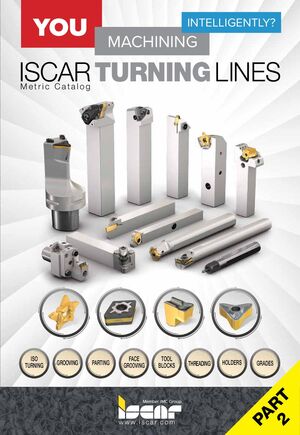 Токарные инструменты Iscar (часть 2) 2026
 Каталог Iscar инструмент для обработки отверстий
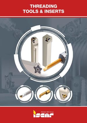 Каталог Iscar державки и пластины для нарезания резьбы 2022
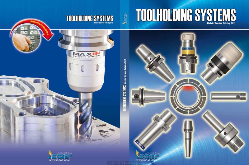 Каталог Iscar крепление инструмента
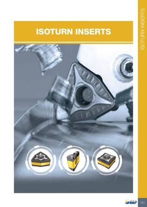 Каталог Iscar токарные пластины ISO 2022
 Руководство Iscar режущий инструмент в производстве штампов и пресс-форм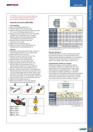
ATTENTION: Cutting tools can break during use. To avoid injury always use safety precautions b a such as gloves, shields and eye protection. Assembly Instructions (BN5-BN9) ¡ β γ ¡ First Assembly
- Clean the toolholder pocket (Fig. 1)
- Clean the reamer head clamping cone Lead Code /
| • Insert the clamping screw into the holder and rotate | β° | a [mm] | g° | b [mm] | ||||
| Parameter | ||||||||
| it 2-3 turns in a clockwise direction (Fig. 2) | ||||||||
| A | 45° | 0.5 | ־ | ־ |
- Clamp the reaming head on the screw; note, BN8
| and BN9 can be assembled only in a specific | B | 25° | 1.07 | ־ | ־ | |
| position relative to the screw (rotate the head | C | 45° | 0.5 | 8° | 0.75 | |
| until locating the correct position) (Fig. 3) | D | 30° | 0.5 | 4° | 1.85 | |
| • Manually rotate the reaming head until | E | 45° | 0.2 | ־ | ־ | |
| it sits firmly in the pocket | F | 90° | ־ | ־ | ־ | |
| • Tighten with the special key (Fig. 4) | G | 75° | 0.15 | ־ | ־ |
- Make sure there is no face gap between the
X Specially Tailored (undesignated) toolholder and the reaming head (Fig. 5) When choosing a reamer, it is important to select a lead geometry that
Indexing covers the reaming allowance.
- Release the reaming head with the key, turning in a counterclockwise direction until it rotates freely Reaming Allowance
- Rotate another one turn by hand Reaming allowance is the stock material which should
- Remove the reamer head from the tool; the be removed by reaming. It is recommended to leave clamping screw should remain inside!!! different reaming allowances depending on the workpiece
- Clean the pocket of the toolholder (Fig. 1) material and the pre-hole quality. Pre-hole should be
- Clean the cone on the new reamer head smooth and straight, without deep scratches on it.
- Clamp the reaming head on the screw; note,
Complementary Grades (on request): BN8 and BN9 can be assembled only in a IC30N cermet tipped, recommended for reaming specific position relative to the screw (rotate the the following materials: non-alloyed (mild) steel, low head until locating the correct position) (Fig. 3) alloyed steel (<5% of alloying elements), free cutting
- Manually rotate the reaming head. In the beginning it
steel, tempered steel (tensile strength <1100 N/mm2) should rotate without the screw and then (after 1/6 of and nodular iron (GGG40, GGG60, etc.) ID5 (PCD) a turn) it should engage with the screw. Rotate until it recommended for high speed reaming of aluminum (special sits firmly in the pocket. If the screw rotates together cases). RN01 (DLC coating) recommended for reaming with the reaming head from the beginning, remove the the following materials: aluminum alloys (cast, wrought, reaming head and open the screw another one turn. etc.), brass, bronze and other nonferrous materials.
- Tighten with the special key (Fig. 4)
- Make sure that there is no face gap between
ØDR the toolholder and the reaming head (Fig. 5) Reaming
1 2 3
4
BN9: 21-23 N*m BN8: 17-20 N*m BN7: 13-15 N*m BN6: 8-10 N*m BN5: 7-8 N*m
5
ØDP Pre-hole Hole Ø mm
| Material | 11.5 - | 13.5 | 16 - | ||||
| < 9.5 9.5 - | >32 | ||||||
| 11.5 | 13.5 | - 16 | 32 | ||||
| Steel and | 0.07- | 0.07- | 0.10- | 0.10- | 0.10- | 0.20- | |
| mm/Ø | |||||||
| Cast Iron | 0.10 | 0.15 | 0.20 | 0.30 | 0.30 | 0.40 | |
| Aluminum | 0.07- | 0.10- | 0.15- | 0.20- | 0.20- | 0.20- | |
| mm/Ø | |||||||
| and Brass | 0.10 | 0.15 | 0.25 | 0.30 | 0.40 | 0.50 |
Δ - Reaming allowance Δ = ∅DR - ∅DP