Каталог Iscar торцевые фрезы 2022 - страница 120
Навигация
 Каталог Iscar сверла со сменной режущей частью 2022
 Каталог Iscar державки и пластины для нарезания резьбы 2022
 Каталог Iscar полирующие фрезы
 Каталог Iscar отрезка 2022
 Каталог Iscar токарный инструмент 2017
 Каталог Iscar монолитные сверла 2022
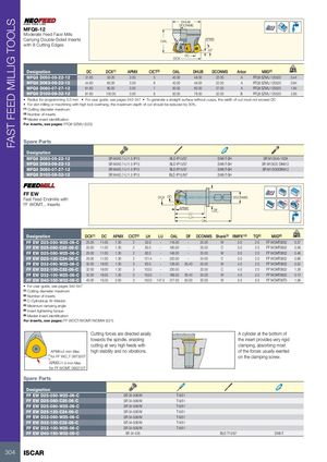
FAST FEED MILLIG TOOLS DHUB DCONMS MFQ8-12 Moderate Feed Face Mills Carrying Double-Sided Inserts OAL APMX with 8 Cutting Edges 22˚ DC DCX Designation DC DCX(1) APMX CICT(2) OAL DHUB DCONMS Arbor MIID(3) kg MFQ8 D050-05-22-12 31.60 50.00 3.00 5 40.00 48.00 22.00 A FFQ8 SZMU 120520 0.44 MFQ8 D063-06-22-12 44.60 63.00 3.00 6 40.00 48.00 22.00 A FFQ8 SZMU 120520 0.84 MFQ8 D080-07-27-12 61.60 80.00 3.00 7 50.00 60.00 27.00 A FFQ8 SZMU 120520 1.84 MFQ8 D100-08-32-12 81.60 100.00 3.00 8 50.00 78.00 32.00 B FFQ8 SZMU 120520 2.95 • Radius for programming 5.0 mm • For user guide, see pages 542-547 • To generate a straight surface without cusps, the width of cut must not exceed DC • For slot milling or machining with high tool overhang, the maximum depth of cut should be reduced by 30%. (1) Cutting diameter maximum (2) Number of inserts (3) Master insert identification For inserts, see pages: FFQ8 SZMU (520) Spare Parts Designation MFQ8 D050-05-22-12 SR M4X0.7-L11.5 IP15 BLD IP15/S7 SW6-T-SH SR M10X40-1638 MFQ8 D063-06-22-12 SR M4X0.7-L11.5 IP15 BLD IP15/S7 SW6-T-SH SR M10X25 DIN912 MFQ8 D080-07-27-12 SR M4X0.7-L11.5 IP15 BLD IP15/S7 SW6-T-SH SR M12X30DIN912 MFQ8 D100-08-32-12 SR M4X0.7-L11.5 IP15 BLD IP15/M7 SW6-T-SH FF EWFast Feed Endmills with DCX DC DCONMS Rd° FF WOMT... Inserts APMX DF LU LH OAL Designation DCX(1) DC APMX CICT(2) LH LU OAL DF DCONMS Shank(3) RMPX°(4) TQ(5) MIID(6) kg FF EW D25-050-W25-06-C 25.00 11.00 1.30 2 53.0 - 118.00 - 25.00 W 5.0 2.0 FF WOMT0602 0.37 FF EW D25-080-C25-06-C 25.00 11.00 1.30 2 83.0 - 180.00 - 25.00 C 5.0 2.0 FF WOMT0602 0.58 FF EW D25-080-W25-06-C 25.00 11.00 1.30 2 83.0 - 148.00 - 25.00 W 5.0 2.0 FF WOMT0602 0.46 FF EW D25-120-C24-06-C 25.00 11.00 1.30 2 121.4 - 220.00 - 24.00 C 5.0 2.0 FF WOMT0602 0.68 FF EW D32-060-W25-06-C 32.00 18.00 1.30 3 63.0 - 128.00 30.40 25.00 W 4.0 2.0 FF WOMT0602 0.52 FF EW D32-100-C32-06-C 32.00 18.00 1.30 3 103.0 - 230.00 - 32.00 C 4.0 2.0 FF WOMT0602 1.28 FF EW D32-100-W25-06-C 32.00 18.00 1.30 3 103.0 - 168.00 30.40 25.00 W 4.0 2.0 FF WOMT0602 0.73 FF EW D40-150-W32-09-C 40.00 19.20 2.00 3 150.0 147.0 217.50 50.00 32.00 W 5.0 5.0 FF WOMT09T3 1.56 • For user guide, see pages 542-547 (1) Cutting diameter maximum (2) Number of inserts (3) C-Cylindrical, W-Weldon (4) Maximum ramping angle (5) Insert tightening torque (6) Master insert identification For inserts, see pages: FF WOCT/WOMT/WOMW (521) Cutting forces are directed axially A cylinder at the bottom of towards the spindle, enabling the insert provides very rigid cutting at very high feeds with clamping, absorbing most APMX=2 mm Max high stability and no vibrations. of the forces usually exerted for FF WO_T 09T320T on the clamping screw. APMX=1.5 mm Max for FF WOMT 060212T Spare Parts Designation FF EW D25-050-W25-06-C SR 34-506/M T-9/51 FF EW D25-080-C25-06-C SR 34-506/M T-9/51 FF EW D25-080-W25-06-C SR 34-506/M T-9/51 FF EW D25-120-C24-06-C SR 34-506/M T-9/51 FF EW D32-060-W25-06-C SR 34-506/M T-9/51 FF EW D32-100-C32-06-C SR 34-506/M T-9/51 FF EW D32-100-W25-06-C SR 34-506/M T-9/51 FF EW D40-150-W32-09-C SR 34-535 BLD T15/S7 SW6-T 304 ISCAR