Каталог Iscar сверла со сменной режущей частью 2022 - страница 79
Навигация
 Каталог Iscar монолитные фрезы 2022
 Каталог Iscar токарный инструмент
 Каталог Iscar инструмент для мелкоразмерной обработки
 Каталог Iscar токарный инструмент для нарезания канавок
 Каталог Iscar полирующие фрезы
 Каталог Iscar дисковые фрезы и фрезерные пластины 2022
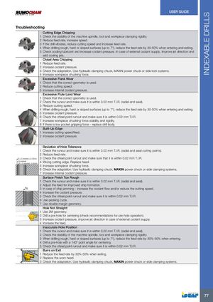
INDEXABLE DRILLS USER GUIDE Troubleshooting Cutting Edge Chipping 1 Check the stability of the machine spindle, tool and workpiece clamping rigidity. 2 Reduce feed rate, increase speed. 3 If the drill vibrates, reduce cutting speed and increase feed rate. 4 When drilling rough, hard or sloped surfaces (up to 7°), reduce the feed rate by 30-50% when entering and exiting. 5 Check cooling lubricant and increase coolant pressure. In case of external coolant supply, improve jet direction and add cooling jets. Chisel Area Chipping 1 Reduce feed rate. 2 Increase coolant pressure. 3 Check the adaptation. Use hydraulic clamping chuck, MAXIN power chuck or side lock systems. 4 Increase workpiece chucking force. Excessive Flank Wear 1 Check that the correct geometry is used. 2 Reduce cutting speed. 3 Increase internal coolant pressure. Excessive Flute Land Wear 1 Check that the correct geometry is used. 2 Check the runout and make sure it is within 0.02 mm T.I.R. (radial and axial). 3 Reduce cutting speed. 4 When drilling rough, hard or sloped surfaces (up to 7°), reduce the feed rate by 30-50% when entering and exiting. 5 Increase coolant pressure. 6 Check the chisel point runout and make sure it is within 0.02 mm T.I.R. 7 Increase workpiece chucking force stability and rigidity. 8 If there is low pocket gripping force - replace drill body. Built-Up Edge 1 Increase cutting speed/feed. 2 Increase coolant pressure. Deviation of Hole Tolerance 1 Check the runout and make sure it is within 0.02 mm T.I.R. (radial and axial cutting points). 2 Reduce feed rate. Ø > D nominal + 0.15mm 3 Check the chisel point runout and make sure that it is within 0.02 mm T.I.R. D nominalØ < D nominal - 0.03mm4 Wrong cutting edge. Replace head. 5 Increase workpiece chucking force. 6 Check the adaptation. Use hydraulic clamping chuck, MAXIN power chuck or side clamping systems. 7 Increase internal coolant pressure. Surface Finish Too Rough 1 Check the runout and make sure it is within 0.02 mm T.I.R. (radial and axial). 2 Adjust the feed for improved chip formation. Ra 3 In case of chip jamming - increase the coolant flow and/or reduce the cutting speed. 4 Increase the coolant pressure. 5 Check the chisel point runout and make sure it is within 0.02 mm T.I.R. 6 Use pecking cycle. 7 Use double margin geometry. Hole Not Straight: 1 Use 2M geometry. 2 Drill a pre-hole for centering (check recommendations for pre-hole operation). 3 Increase coolant pressure, improve jet direction in case of external coolant supply. 4 Increase the feed. Inaccurate Hole Position 1 Check the runout and make sure it is within 0.02 mm T.I.R. (radial and axial). 2 Check the stability of the machine spindle, tool and workpiece clamping rigidity. 3 When drilling rough, hard or sloped surfaces (up to 7°), reduce the feed rate by 30%-50% when entering. 4 Drill a pre-hole with a 140° point angle for centering. 5 Check the chisel point runout and make sure it is within 0.02 mm T.I.R. Burrs on Exit 1 Reduce the feed rate by 30%-50% when exiting. 2 Replace the worn head. 3 Check the adaptation. Use hydraulic clamping chuck, MAXIN power chuck or side clamping systems. 77