Каталог Iscar сверла со сменной режущей частью 2022 - страница 123
Навигация
 Каталог Iscar монолитные фрезы 2022
 Каталог Iscar токарный инструмент
 Каталог Iscar инструмент для мелкоразмерной обработки
 Каталог Iscar токарный инструмент для нарезания канавок
 Каталог Iscar полирующие фрезы
 Каталог Iscar дисковые фрезы и фрезерные пластины 2022
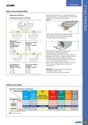
INDEXABLE DRILLS USER GUIDE Setup of Non-Rotating Drills Machining Conditions Make sure the center line of the drill is aligned with the spindle center line. It is recommended to verify the setup Optimizing Chip Shape for DR Drills according to the instructions shown below. DR-06 L L1 h2 h1 D-0.3 (mm) DT GF D+1 (mm) Under regular conditions it is possible to adjust the center line of the drill (X-axis of the machine) in order to change hole diameter size. General use For ISO – P/M/K/H/S For low up to medium materials feed rates For medium up to For ISO – P material high feed rates L – close L – open H2 – highH2 – lowL1 – small CORE L1 – medium H1 – deep H1 – shallow 1 Drill a hole 6 mm deep with the drill center AL HD line aligned with the spindle center line.2 Check the existing core. If there is no core, check the alignment of the Y-axis of the drill and spindle. Correct by checking the adapter or adjusting the Y-axis. 3 Check that the hole diameter equals the drill diameter +0.0- +0.2 mm. If not, adjust the X-axis. 4 Note: In some operations, part of the core may break. For medium up to For low up to medium If this occurs, use finger contact to verify if any high feed rates feed rates core remains For ISO – N material For ISO – P material L – open L – openH2 – highH2 – high Warning: As the drill goes all the way through L1 – non L1 – non a workpiece, it ejects a disc. H1 – deep H1 – non For worker safety, guards should be used.. Drilling Insert Grades Grades for Applications and Materials Material Groups ISO P ISO M ISO K ISO N ISO S ISO H 1-11 12-13 14 15-20 21-28 31-37 38-41 Stainless Main Applications Steel SteelFerritic &Stainless SteelAustenitic & Duplex(Ferritic-Austenitic)Cast IronNonferrousHighTempHardSteelMartensitic Harder IC808 (908) IC808 (908) IC808 (908) IC8080(1) (9080) IC808 (908) IC808 (908) IC808 (908) DRILLING IC5500 IC808 (908) Tougher (1) Use for an outer insert on DR drills Default recommendation 121