Каталог Iscar сверла со сменной режущей частью 2022 - страница 121
Навигация
 Каталог Iscar монолитные фрезы 2022
 Каталог Iscar токарный инструмент
 Каталог Iscar инструмент для мелкоразмерной обработки
 Каталог Iscar токарный инструмент для нарезания канавок
 Каталог Iscar полирующие фрезы
 Каталог Iscar дисковые фрезы и фрезерные пластины 2022
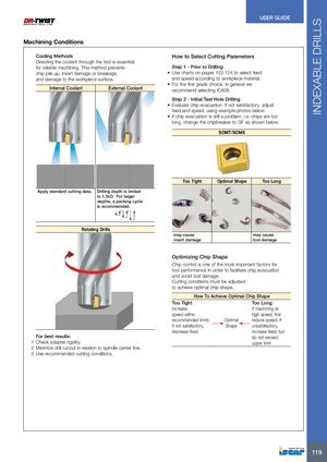
INDEXABLE DRILLS USER GUIDE Machining Conditions Cooling Methods How to Select Cutting Parameters Directing the coolant through the tool is essential for reliable machining. This method prevents Step 1 - Prior to Drilling chip pile up, insert damage or breakage, • Use charts on pages 122-124 to select feed and damage to the workpiece surface. and speed according to workpiece material. • For the first grade choice, in general we Internal Coolant External Coolant recommend selecting IC808. Step 2 - Initial Test Hole Drilling • Evaluate chip evacuation. If not satisfactory, adjust feed and speed, using example photos below. • If chip evacuation is still a problem, i.e. chips are too long, change the chipbreaker to GF as shown below. SOMT/SOMX Too Tight Optimal Shape Too Long Apply standard cutting data. Drilling depth is limited to 1.5xD. For larger depths, a pecking cycle is recommended. Rotating Drills may cause may cause insert damage tool damage Optimizing Chip Shape Chip control is one of the most important factors for tool performance in order to facilitate chip evacuation and avoid tool damage. Cutting conditions must be adjusted to achieve optimal chip shape. How To Achieve Optimal Chip Shape Too Tight Too Long Increase If machining at speed within high speed, first recommended limits. Optimal reduce speed. If If not satisfactory, Shape unsatisfactory, decrease feed. increase feed, but For best results: do not exceed 1 Check adapter rigidity. upper limit. 2 Minimize drill runout in relation to spindle center line. 3 Use recommended cutting conditions. 119