Каталог Iscar расточные системы 2022 - страница 102
Навигация
 Каталог Iscar дисковые фрезы и фрезерные пластины 2022
 Каталог Iscar монолитные концевые фрезы и система multi-master
 Каталог Iscar расточные системы
 Каталог Iscar крепление инструмента
 Каталог Iscar решения для глубокого сверления
 Каталог Iscar инструмента для сверления
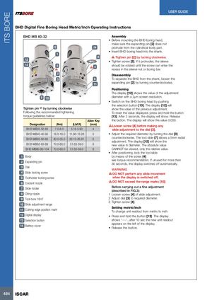
ITS BORE USER GUIDE BHD Digital Fine Boring Head Metric/Inch Operating Instructions BHD MB 80-32 Assembly • Before mounting the BHD boring head, make sure the expanding pin [2] does not 2 14 protrude from the cylindrical body part. • Insert BHD boring head into the shank. 1 8 Tighten pin [2] by turning clockwise. 12 • Tighten screw [5]. If it protrudes, the sleeve 13 3 4 should be rotated until the screw can enter the recess in the sleeve nut or boring bar. 77 Disassembly 55 6 To separate the BHD from the shank, loosen the 11 expanding pin [2] by turning counterclockwise. Positioning The display [12] shows the value of the adjustment 9 10 diameter with a 2µm screen resolution. • Switch on the BHD boring head by pushing the selection button [13]. The display [12] will Tighten pin (2) by turning clockwise show the value of the previous adjustment. Following the recommended tightening To reset the value displayed, press and hold the button torque guidelines below: [13]. After 2 seconds, the display will show. Release Allen Key the button. The display will show the value 0.000. Designation (Nm) (Lbf.ft) (mm) Loosen screw [4] before making any BHD MB32-32-83 7.0-8.0 5.16-5.90 4 slide adjustment to the dial [3]. BHD MB40-40-90 16.0-18.0 11.80-13.28 5 • Adjust the required diameter by turning the dial [3] BHD MB50-50-60 30.0-35.0 22.13-25.81 6 counterclockwise. The tool slide [7] allows a 5mm radial adjustment. The display [12] will show the BHD MB63-63-89 70.0-80.0 51.63-59.0 8 new value in diameter. The absolute value BHD MB80-80-104 70.0-80.0 51.63-59.0 8 CANNOT be viewed, only the relative value. • After positioning, lock the tool slide 1 Body by means of the screw [4] 2 Expanding pin see torque recommendation. If unused for more than30 seconds, the display switches off automatically. 3 Dial WARNINIG 4 Slide locking screw DO NOT perform any slide movement 5 Toolholder locking screw when the display is switched off. 6 Coolant nozzle DO NOT exceed the range marks [10]. 7 Slide holder Before carrying out a fine adjustment(described in FIG.3): 8 Oiling nipple 1 Loosen screw [4] of slide adjustment. 9 Tool bore 16H7 2 Adjust dial [3] to required diameter. 3 Tighten screw [4]. 10 Slide adjustment range 11 Cutting edge position mark Setting metric/inchTo change unit readout from metric to inch: 12 Digital display • Press and hold the button [13]. The display 13 Selection button shows “----”, after 10 sec the new unit readout 14 Battery cover appears on the left of the display.•Release the button. 484 ISCAR