Каталог Iscar отрезка 2022 - страница 80
Навигация
 Токарные инструменты Iscar (часть 1) 2026
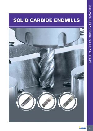 Каталог Iscar монолитные фрезы 2022
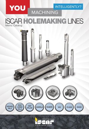 Инструменты для обработки отверстий Iscar 2026
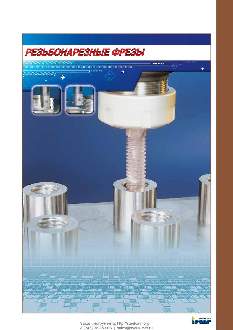 Каталог Iscar резьбонарезные фрезы
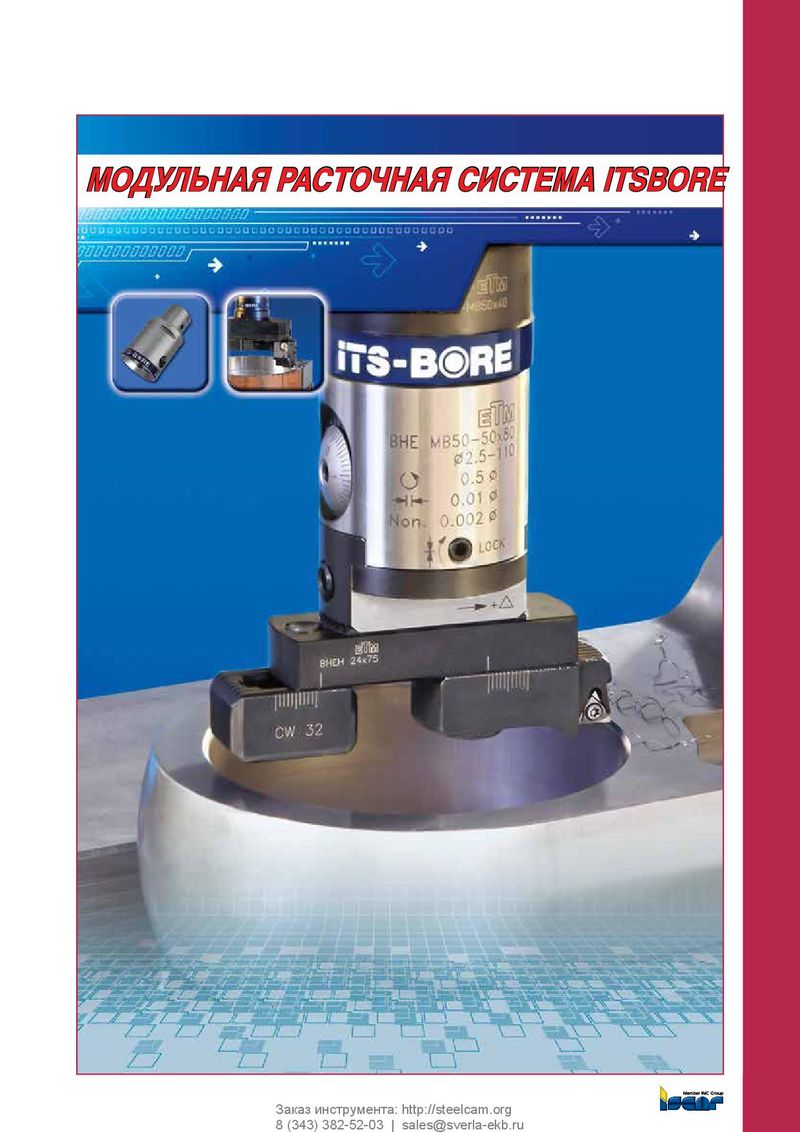 Каталог Iscar расточные системы
 Каталог Iscar токарный инструмент 2017
Parting and Grooving
| Selection of Inserts | Insert Support |
| For a proper match of insert and cutting | A self-clamped tool is recommended for deep radial |
| material to application, the following variables | machining. A screw-clamp holder is recommended |
| must be taken into consideration: | for axial and small D.O.C. machining. |
- Width of cut (width of insert)
90˚ Mounting
- Chipformer style
- Lead angle It is very important that the insert is mounted at 90º
- Corner radius to the center line of the workpiece in order to obtain
- Carbide grade perpendicular surfaces and reduce the risk of vibration. Width of Cut (W.O.C.) and Depth of Cut (D.O.C.) Workpiece Machinability In selecting W.O.C., the main factor to consider is the The workpiece material affects all of the above factors. required D.O.C. The ratio D.O.C.≈ 8xW.O.C. is of practical use on alloy steel of average machinability. For example, Machine Power and Setup Rigidity applying a 3 mm W.O.C. insert TAG N3C to cut-off a
Excessive W.O.C. on a light-duty machine will yield 48 mm solid bar. vibration and may even stop spindle rotation. Additional factors which affect D.O.C.
| capacity, relative to the ratio, are: | Expensive Workpiece Material |
| Holder or Blade Size | On costly metals the narrowest applicable |
W.O.C. should be used. To minimize risk of vibration and deflection always choose:
- Blade or toolholder with smallest possible overhang.
- Toolholder with maximum shank dimension.
- Blade height (B) dimension which is larger than Tmax.
- Blade or holder with maximum blade width (largest possible insert seat size). Example:
- A W.O.C. 9.5 mm on blade TGFH 53K-9
- (B=52.6 mm) extends the ratio of D.O.C. to W.O.C. by some 50% to 120 mm.
0.1/1000 Tmax 90° ±10'