Каталог Iscar отрезка 2022 - страница 60
Навигация
 Токарные инструменты Iscar (часть 1) 2026
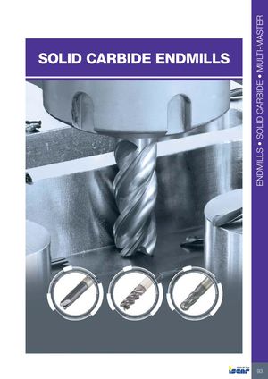 Каталог Iscar монолитные фрезы 2022
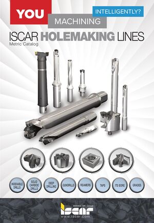 Инструменты для обработки отверстий Iscar 2026
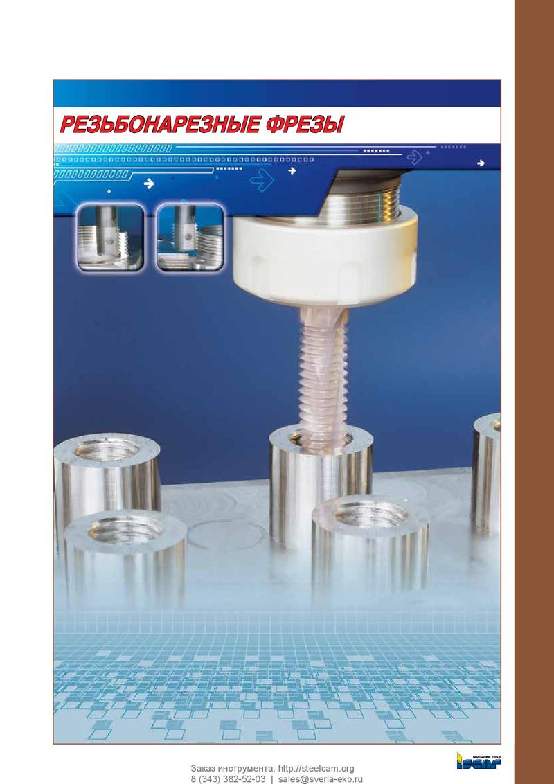 Каталог Iscar резьбонарезные фрезы
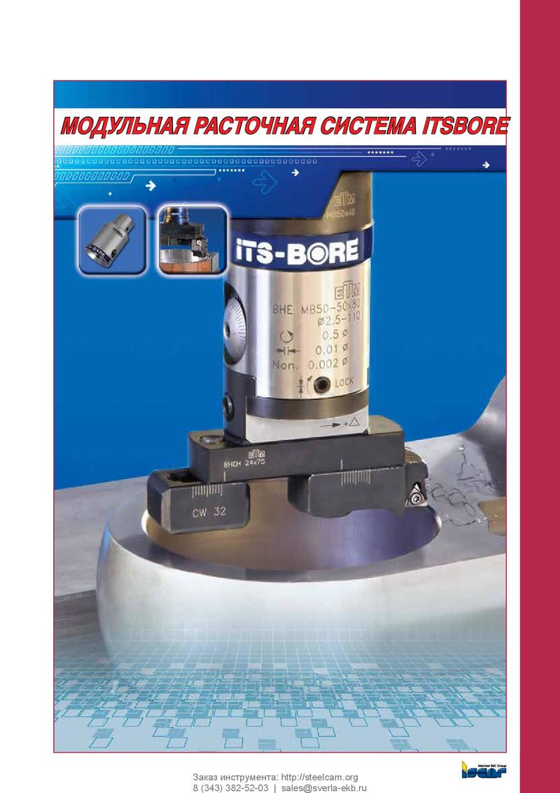 Каталог Iscar расточные системы
 Каталог Iscar токарный инструмент 2017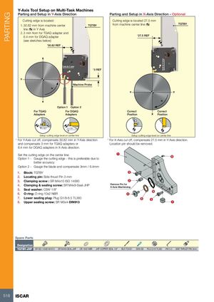
Y-Axis Tool Setup on Multi-Task Machines
Parting and Setup in Y-Axis Direction Parting and Setup in X-Axis Direction - Optional
Cutting edge is located: Cutting edge is located 27.5 mm
1. 30.82 mm from machine center from machine center line ( ) TGTBY
TGTBY line ( ) in Y Axis 2. 3 mm from for TGAQ adapter and 6.4 mm for DGAQ adapter *27.5 REF
(see sketches below) *30.82 REF
X
Feed (in Y axis) *3 REF
Y Machine Probe n Y Y
X n Option 1 Option 2
| For TGAQ | For DGAQ | Correct | Correct | |
| Adapters | Adapters | Position | X | Position |
3 REF 6.4 REF Setup cutting edge level on center line Setup cutting edge level on center line * For Y-Axis cut off, compensate 30.82 mm in Y-Axis direction * For X-Axis cut off, compensate 27.5 mm in Y-Axis direction. and compensate 3 mm for TGAQ adapters or Location pin should be removed. 6.4 mm for DGAQ adapters in X-Axis direction. Set the cutting edge on the center line: 1 8 Option 1 - Gauge the cutting edge - this is preferable due to better accuracy Option 2 - Gauge the blade and compensate 3mm / 6.4mm
| 1. | Block: TGTBY | 3 |
| 2. | Locating pin: Side thrust Pin 3 mm | |
| 3. | Clamping screw : SR M4x10 ISO 14580 | 2 |
| 4. | Clamping & sealing screw: SR M4x9-Seal-JHP | Remove Pin for |
| X-Axis Machinning | ||
| 5. | Seal washer: CSW 1/8’’ | |
| 6 | ||
| 6. | O-ring: O-ring 10x2 NBR | 4 |
| 7. | Lower sealing plug: Plug G1/8-6.5 TL360 | 5 |
| 3 | ||
| 8. | Upper sealing screw: SR M3x4-DIN913 | 7 |
Spare Parts
Designation
TGTBY-JHP SR ISO 14580 M4X10 SR M4X9-SEAL-JHP OR 16X2 NBR JHP COPPER SEAL 1/8" BLD T20/S7 SW6-SD PLG G1/8 TL360 HW 5.0 SIDE THRUST PIN 3mm