Каталог Iscar обработка канавок 2022 - страница 86
Навигация
 Каталог Iscar монолитные концевые фрезы и система multi-master
 Каталог Iscar сверла ружейные и для глубокого сверления 2022
 Каталог Iscar токарные державки ISO 2022
 Каталог Iscar инструмент для обработки алюминиевых колёс
 Каталог Iscar инструментальная оснастка 2022
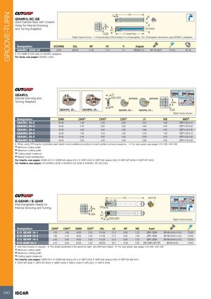
GROOVE-TURN
f1 OAL HF
GHAIR/L-SC-GE
Solid Carbide Bars with Coolant
Holes for Internal Grooving DMIN
and Turning Adapters WF DCONMS
CDX LF (assembly)
Right-hand shown • LF(assembly)=OAL(holder)-f1+LF(aadapter). For LF(adapter) dimension,see GEAIR/L adapters
Designation DCONMS OAL WF HF f1 Adapter
GHAIR/L 25SC-25 25.00 200.00 17.00 11.5 2.4 GEAIR/L 25-... SR 16-236 P T-15/5 PL 25
• For DMIN & CDX refer to GEAIR/L adapters.
For tools, see pages: GEAIR/L (340)
GEAIR/L LF
Internal Grooving and CWN-CWX GEPI/GEMI.. GEPI/GEMI..
Turning Adapters DMIN
WB
GEAIR/L 20-... GEAIR/L 25-... CDX
Right-hand shown
Designation DMIN CWN(1) CWX(2) CDX(3) LF WB MIID(4)
GEAIR/L 20-2 20.00 1.90 2.40 3.00 3.40 1.60 GEPI 2.00-0.10
GEAIR/L 20-3 20.00 2.40 3.00 3.00 3.60 2.00 GEPI 3.00-0.20
GEAIR/L 20-4 20.00 3.00 4.00 3.00 3.90 2.50 GEPI 3.18-0.20
GEAIR/L 25-2 25.00 1.90 2.40 4.00 3.40 1.60 GEPI 2.00-0.10
GEAIR/L 25-3 25.00 2.40 3.00 4.00 3.60 2.00 GEPI 3.00-0.20
GEAIR/L 25-4 25.00 3.00 4.00 4.00 3.90 2.50 GEPI 3.18-0.20
• When using TIPI inserts, toolholder seat needs to be modified according to insert profile to ensure clearance • For user guide, see pages 419-428, 432-436
(1) Minimum cutting width
(2) Maximum cutting width
(3) Cutting depth maximum
(4) Master insert identification
For inserts, see pages: GEMI (341) • GEMI (full radius) (341) • GEPI (342) • GEPI (full radius) (342) • GEPI-MT (648) • GEPI-WT (642)
For holders, see pages: C#-GHAIR/L (629) • GHAIR/L-GE (339) • GHAIR/L-SC-GE (340)
OAL WF
E-GEHIR / E-GHIR LH
Interchangeable Heads for
Internal Grooving and Turning WBDMIN
CDX WF
CWN-CWX Right-hand shown
Designation CWN(1) CWX(2) DMIN CDX(3) OAL LH WF WB Insert
E12 GEHIR 16-1 1.50 1.90 16.00 2.20 174.00 21.0 9.00 1.20 GEPI, GEMI SR M5-04451-L10.5 T-20/5
E12 GEHIR 16-2 1.90 2.40 16.00 2.20 174.00 21.0 9.00 1.60 GEPI, GEMI SR M5-04451-L10.5 T-20/5
E12 GEHIR 16-3 2.40 3.00 16.00 2.20 174.00 21.0 9.00 2.00 GEPI, GEMI SR M5-04451-L10.5 T-20/5
E16 GHIR 25-3 2.40 3.00 25.00 4.00 209.00 28.7 12.80 2.00 GIPI,GIMIY,GIFI,TIPI SR M5-04451 T-20/5
• Left-hand heads on request • The shank assembly is the same for right- and left-hand heads • For user guide, see pages 419-428, 432-436
(1) Minimum cutting width
(2) Maximum cutting width
(3) Cutting depth maximum
For inserts, see pages: GEMI (341) • GEMI (full radius) (341) • GEPI (342) • GEPI (full radius) (342) • GEPI (W