Каталог Iscar обработка канавок 2022 - страница 79
Навигация
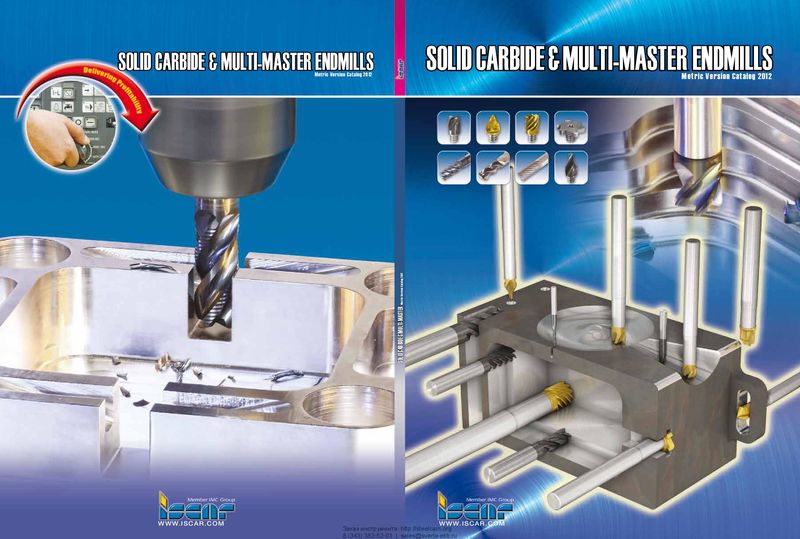 Каталог Iscar монолитные концевые фрезы и система multi-master
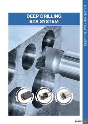 Каталог Iscar сверла ружейные и для глубокого сверления 2022
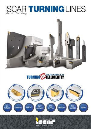 Каталог Iscar токарные державки ISO 2022
 Каталог Iscar инструмент для обработки алюминиевых колёс
 Каталог Iscar инструментальная оснастка 2022
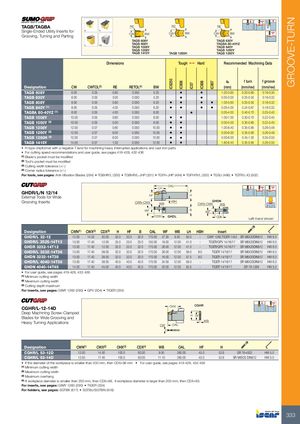
IC8250 IC808 IC07 IC806 IC807 GROOVE-TURN TAGB/TAGBA RE RE RE Single-Ended Utility Inserts forGrooving, Turning and Parting CW BW CW BW CW BW TAGB 608Y TAGB 630Y TAGB 808Y TAGBA 80-40YZ TAGB 1008Y TAGB 840Y TAGB 1208Y TAGB 1050Y TAGB 1415Y TAGB 1260H TAGB 1260Y Dimensions Tough 1 Hard Recommended Machining Data ap f turn f groove Designation CW CWTOL(3) RE RETOL(4) BW (mm) (mm/rev) (mm/rev) TAGB 608Y 6.00 0.05 0.80 0.050 5.20 • • 1.00-3.60 0.20-0.60 0.18-0.30 TAGB 630Y 6.00 0.05 3.00 0.050 5.20 • • 0.00-3.00 0.25-0.55 0.18-0.32 TAGB 808Y 8.00 0.05 0.80 0.050 6.20 • • • • 1.00-5.60 0.25-0.55 0.18-0.32 TAGB 840Y (1) 8.00 0.05 4.00 0.050 6.20 • • • • 0.00-4.00 0.24-0.67 0.18-0.32 TAGBA 80-40YZ (1) 8.00 0.05 4.00 0.050 6.00 • 0.00-4.00 0.40-0.70 0.25-0.40 TAGB 1008Y 10.00 0.05 0.80 0.050 8.00 • • 1.00-7.00 0.30-0.70 0.22-0.40 TAGB 1050Y (2) 10.00 0.05 5.00 0.050 8.00 • • 0.00-5.00 0.30-0.85 0.22-0.40 TAGB 1208Y 12.00 0.07 0.80 0.050 10.00 • • 1.00-8.40 0.35-0.85 0.26-0.48 TAGB 1260Y (2) 12.00 0.07 6.00 0.050 10.00 • • 0.00-6.00 0.35-0.90 0.26-0.48 TAGB 1260H (2) 12.00 0.07 6.00 0.050 10.00 • • 0.00-6.00 0.45-1.00 0.35-0.55 TAGB 1415Y 14.00 0.07 1.50 0.050 12.00 • • 1.80-8.40 0.35-0.85 0.26-0.50 • H-type chipformer with a negative T-land for machining heavy interrupted applications and cast iron parts • For cutting speed recommendations and user guide, see pages 419-428, 432-436 (1) Blade's pocket must be modified (2) Tool's pocket must be modified (3) Cutting width tolerance (+/-) (4) Corner radius tolerance (+/-) For tools, see pages: Anti-Vibration Blades (284) • TGBHR/L (330) • TGBHR/L-JHP (331) • TGFH-JHP (494) • TGFH/R/L (332) • TGSU (496) • TGTR/L-IQ (502) OAL LH GHDR/L/N 12/14 External Tools for Wide HF H Grooving Inserts CWN-CWX WB HBH GHDNCWN-CWXWB WF B WF CDX GHDL CDX Left-hand shown Designation CWN(1) CWX(2) CDX(3) H HF B OAL WF WB LH HBH Insert GHDR/L 32-12 12.00 14.53 30.00 32.0 32.0 32.0 170.00 27.30 9.50 50.0 - GIMY 1260,TIGER 1453 SR M8X20DIN912 HW 6.0 GHDR/L 2525-14T12 13.00 17.40 12.00 25.0 25.0 25.0 150.00 19.00 12.00 41.0 - TIGER/GPV 14/16/17 SR M8X20DIN912 HW 6.0 GHDR 3232-14T12 13.00 17.40 12.00 32.0 32.0 32.0 170.00 26.00 12.00 41.0 - TIGER/GPV 14/16/17 SR M8X20DIN912 HW 6.0 GHDR/L 3232-14T38 13.00 17.40 38.00 32.0 32.0 32.0 170.00 26.00 12.00 59.0 8.0 TIGER 14/16/17 SR M8X20DIN912 HW 6.0 GHDN 3232-14T38 13.00 17.40 38.00 32.0 32.0 32.0 170.00 16.00 12.00 57.5 8.0 TIGER 14/16/17 SR M8X20DIN912 HW 6.0 GHDR/L 4040-14T38 13.00 17.40 38.00 40.0 40.0 40.0 170.00 34.00 12.00 59.0 - TIGER 14/16/17 SR M8X20DIN912 HW 6.0 GHDN 4040-14T45 14.50 17.40 45.00 40.0 40.0 40.0 170.00 20.00 12.00 55.5 - TIGER 14/16/17 SR 76-1289 HW 5.0 • For user guide, see pages 419-428, 432-436 (1) Minimum cutting width (2) Maximum cutting width (3) Cutting depth maximum For inserts, see pages: GIMY 1260 (290) • GPV (304) • TIGER (334) CGHR/L-12-14D OHX CGHR Deep Machining Screw-Clamped Blades for Wide Grooving and H HF Heavy Turning Applications WBCWOAL Designation CWN(1) CWX(2) OHX(3) CDX(4) WB OAL HF H CGHR/L 53-12D 12.00 14.50 100.0 93.00 9.50 260.00 45.0 52.6 SR 76-4002 HW 5.0 CGHR/L 53-14D 12.50 17.40 100.0 93.00 11.10 260.00 45.0 52.6 SR M6X25 DIN912 HW 5.0 • If the diameter of the workpiece is smaller than 200 mm, then CDX=98 mm • For user guide, see pages 419-428, 432-436 (1) Minimum cutting width (2) Maximum cutting width (3) Maximum overhang (4) If workpiece diameter is smaller than 200 mm, then CDX=98, if workpiece diameter is larger than 200 mm, then CDX=93. For inserts, see pages: GIMY 1260 (290) • TIGER (334) For holders, see pages: SGTBK (617) • SGTBU/SGTBN (616) 333