Каталог Iscar обработка канавок 2022 - страница 28
Навигация
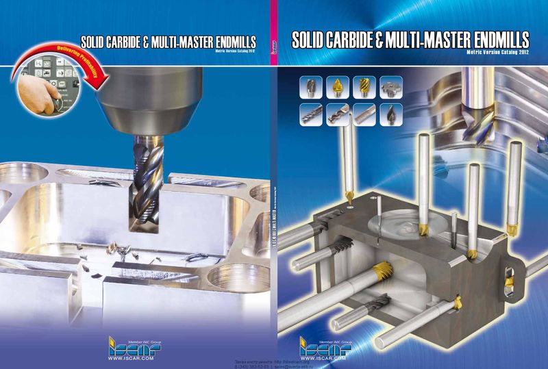 Каталог Iscar монолитные концевые фрезы и система multi-master
 Фрезерные инструменты Iscar 2026
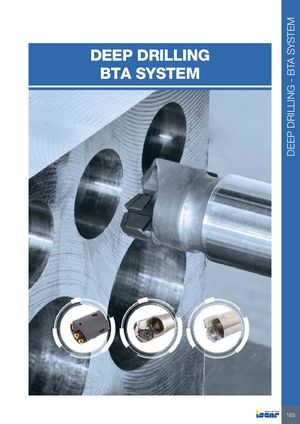 Каталог Iscar сверла ружейные и для глубокого сверления 2022
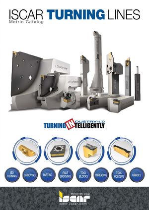 Каталог Iscar токарные державки ISO 2022
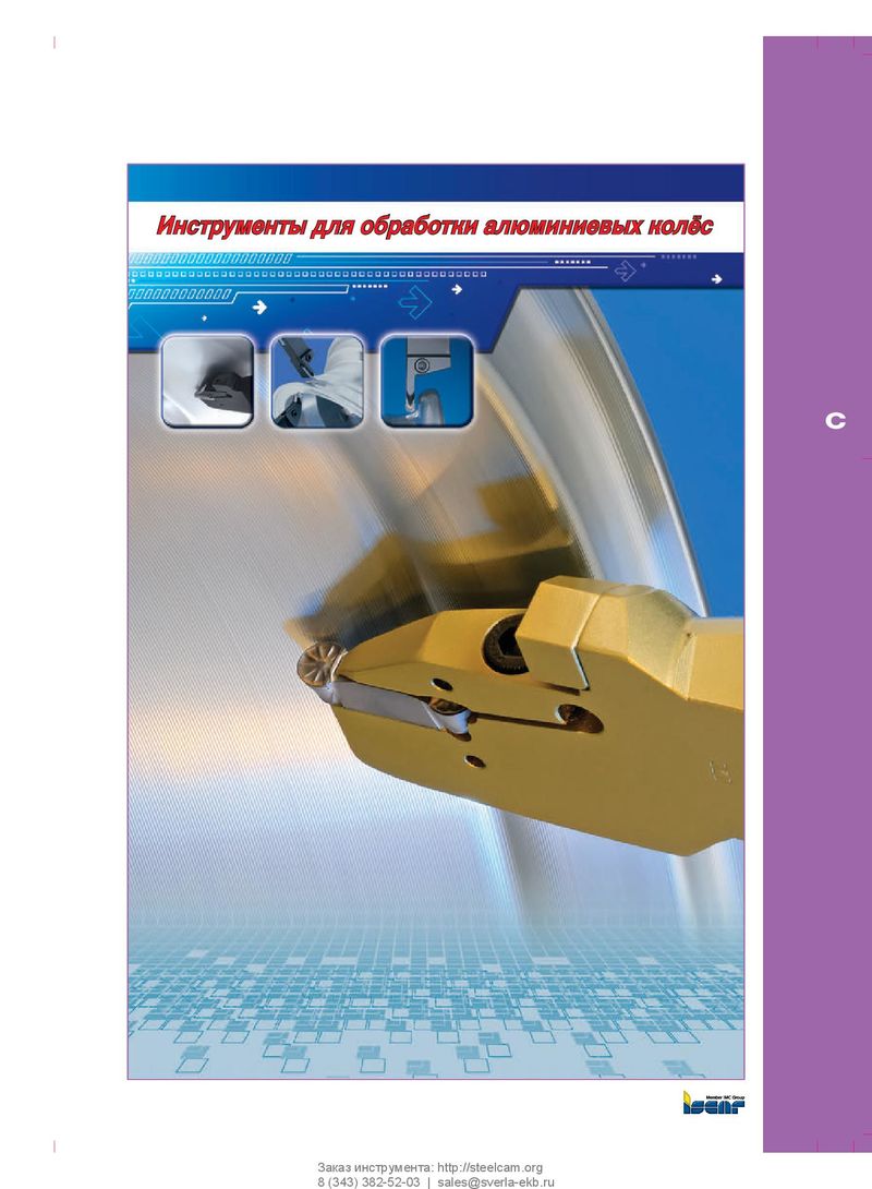 Каталог Iscar инструмент для обработки алюминиевых колёс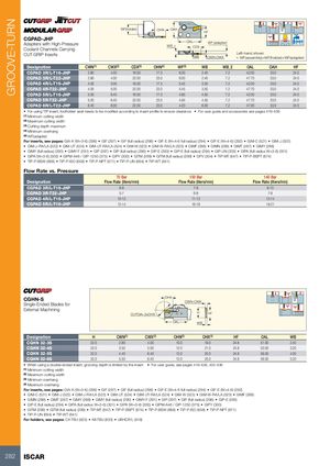
| WF | (holder) | OHN | OAH | HF | ||||||
| CGPAD-JHP Adapters with High-Pressure Coolant Channels Carrying CUT-GRIP Inserts | WB2 | OAL WB C CDX W | WN-CWX F (adapter) | Left-hand sho •WF(assembl | wn y)=WF(hold | er)+WF(adapter) Bar Max | ||||
| Designation | CWN(1) | CWX(2) | CDX(3) | OHN(4) | WF(5) | WB | WB2 | OAL | OAH | HF |
| CGPAD 3R/L-T16-JHP | 2.80 | 4.00 | 16.00 | 17.3 | 6.00 | 2.40 | 7.2 | 42.00 | 33.0 | 24.0 |
| CGPAD 3R/L-T22-JHP | 2.80 | 4.00 | 22.00 | 23.0 | 6.00 | 2.40 | 7.2 | 47.70 | 33.0 | 24.0 |
| CGPAD 4R/L-T16-JHP | 4.00 | 5.00 | 16.00 | 17.3 | 5.45 | 3.50 | 7.2 | 42.00 | 33.0 | 24.0 |
| CGPAD 4R-T22-JHP | 4.00 | 5.00 | 22.00 | 23.0 | 5.45 | 3.50 | 7.2 | 47.70 | 33.0 | 24.0 |
| CGPAD 5R/L-T16-JHP | 5.00 | 6.40 | 16.00 | 17.3 | 4.95 | 4.50 | 7.2 | 42.00 | 33.0 | 24.0 |
| CGPAD 5R-T22-JHP | 5.00 | 6.40 | 22.00 | 23.0 | 4.95 | 4.50 | 7.2 | 47.70 | 33.0 | 24.0 |
| CGPAD 8R/L-T22-JHP | 6.40 | 8.00 | 22.00 | 23.0 | 4.20 | 6.00 | 7.2 | 47.00 | 33.0 | 24.0 |
- For using TIP insert, toolholder seat needs to be modified according to insert profile to ensure clearance
- For user guide and accessories see pages 419-436
(1) Minimum cutting width (2) Maximum cutting width (3) Cutting depth maximum (4) Minimum overhang (5) WF(adapter)
For inserts, see pages: GIA-K (W=3-6) (298) GIF (297) GIF (full radius) (298) GIF-E (W=4-6 full radius) (294) GIF-E (W=4-6) (292) GIM-C (521) GIM-J (522)
- GIM-J-RA/LA (522)
- GIM-UT (524)
- GIM-UT-RA/LA (524)
- GIM-W (523)
- GIM-W-RA/LA (523)
- GIMF (288)
- GIMN (289)
- GIMT (287)
- GIMY (288)
- GIMY (full radius) (290)
- GIMY-F (291)
- GIP (297)
- GIP (full radius) (296)
- GIP-E (293)
- GIP-E (full radius) (294)
- GIP-UN (303)
- GIPA (full radius W=3-6) (301)
- GIPA (W=3-6) (300)
- GIPM-A46 / GIP-1250 (375)
- GIPY (300)
- GITM (299)
- GITM (full radius) (299)
- GPV (304)
- TIP-MT (647)
- TIP-P-BSPT (674)
- TIP-P-BSW (668)
- TIP-P-ISO (658)
- TIP-P-NPT (671)
- TIP-P-UN (664)
- TIP-WT (641)
Flow Rate vs. Pressure
| Designation | 70 Bar Flow Rate(liters/min) | 100 Bar Flow Rate(liters/min) | 140 Bar Flow Rate(liters/min) |
| CGPAD 3R/L-T16-JHP | 6-8 | 7-9 | 8-10 |
| CGPAD 3R-T22-JHP | 5-7 | 6-8 | 7-9 |
| CGPAD 4R/L-T16-JHP | 10-12 | 11-13 | 12-14 |
| CGPAD 5R/L-T16-JHP | 12-14 | 16-18 | 19-21 |
| CGHN-S Single-Ended Blades for External Machining | CU | TDIA=2xOHX | OHX OAL CWN | WB H HF -CWX | ||||
| Designation | H | CWN(1) | CWX(2) | OHN(3) | OHX(4) | HF | OAL | WB |
| CGHN 32-3S | 32.0 | 2.80 | 4.00 | 10.0 | 19.0 | 24.8 | 51.00 | 2.40 |
| CGHN 32-4S | 32.0 | 3.50 | 5.00 | 12.0 | 21.0 | 24.8 | 53.00 | 3.20 |
| CGHN 32-5S | 32.0 | 4.40 | 6.40 | 12.0 | 25.0 | 24.8 | 56.00 | 4.00 |
| CGHN 32-6S | 32.0 | 5.50 | 6.40 | 12.0 | 25.0 | 24.8 | 56.00 | 5.20 |
- When using a double-ended insert, grooving depth is limited by the insert
- For user guide, see pages 419-428, 432-436
(1) Minimum cutting width (2) Maximum cutting width (3) Minimum overhang (4) Maximum overhang
For inserts, see pages: GIA-K (W=3-6) (298) GIF (297) GIF (full radius) (298) GIF-E (W=4-6 full radius) (294) GIF-E (W=4-6) (292)
- GIM-C (521)
- GIM-J (522)
- GIM-J-RA/LA (522)
- GIM-UT (524)
- GIM-UT-RA/LA (524)
- GIM-W (523)
- GIM-W-RA/LA (523)
- GIMF (288)
- GIMN (289)
- GIMT (287)
- GIMY (288)
- GIMY (full radius) (290)
- GIMY-F (291)
- GIP (297)
- GIP (full radius) (296)
- GIP-E (293)
- GIP-E (full radius) (294)
- GIPA (full radius W=3-6) (301)
- GIPA (W=3-6) (300)
- GIPM-A46 / GIP-1250 (375)
- GIPY (300)
- GITM (299)
- GITM (full radius) (299)
- TIP-MT (647)
- TIP-P-BSPT (674)
- TIP-P-BSW (668)
- TIP-P-ISO (658)
- TIP-P-NPT (671)
- TIP-P-UN (664)
- TIP-WT (641)
For holders, see pages: C#-TBU (623) IM-TBU (633) UBHCR/L (618)