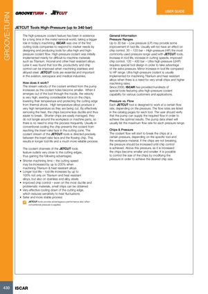
| The high-pressure coolant feature has been in existence | General Information |
| for a long time in the metal removal world, taking a bigger | Pressure Ranges |
| role in today’s machining. ISCAR was one of the first | Up to 30 bar – Low pressure (LP) may provide some |
| cutting tools companies to respond to market needs by | improvement in tool life. Usually will not have an effect on |
| designing and producing tools for ultra-high and high- | chip control. 30 – 120 bar – High-pressure (HP) the most |
| pressure coolant flow. High-pressure coolant was initially | commonly used pressure range used with JETCUT tools. |
| implemented mainly for difficult-to-machine materials | Increase in tool life, increase in cutting speeds, improved |
| such as Titanium, Inconel and other heat resistant alloys. | chip control. 120 – 400 bar – Ultra high-pressure (UHP) |
| Later it was found that tool life, productivity and chip | requires special tool design in order to take advantage |
| control can be improved when machining stainless and | of the extra pressure. Minor increase in tool life compared |
| alloyed steel. JETCUT tools are essential and important | to HP range. Ultra high-pressure coolant is usually |
| in the aviation, aerospace and medical industries. | implemented for machining Titanium and heat resistant |
| alloys when there is a need for very small chips and higher |
| How does it work? | machining rates. |
| The stream velocity of the coolant emitted from the pump | Since 2000, ISCAR has provided hundreds of |
| increases as the coolant holes become smaller. When it | special tools featuring ultra high-pressure coolant |
| emerges out of the tool through the nozzle, the velocity | capability for various customers and applications. |
| is very high, exerting considerable force on the chips, | |
| lowering their temperature and protecting the cutting edge | Pressure vs. Flow |
| from thermal shock. High temperature alloys produce a | Each JETCUT tool is designed to work at a certain flow |
| very high temperature as they are being cut. By effectively | rate, depending on the pressure. The flow rates are listed |
| removing the heat, the chips become less ductile and thus | in the catalog pages for each tool. The user should verify |
| easier to break. Shorter chips are easily managed, they | that the pump can supply the required flow in order to |
| do not tangle around the workpiece or machine parts, so | achieve the optimal results. The pump data sheet will |
| there is no need to stop the process frequently. Usually in | usually list the maximum flow rate for each pressure range. |
| conventional cooling the chip prevents the coolant from | |
| reaching the insert rake face in the cutting zone. The | Chips & Pressure |
| coolant stream of the JETCUT tools is directed precisely | The coolant flow will start to break the chips at a |
| between the insert rake face and the flowing chip. This | certain pressure, depending on the specific tool and |
| results in longer tool life and a much more reliable process. | the workpiece material. If the chips are not breaking, |
| the pressure should be increased until chip control |
| The coolant channels of the JETCUT tools | is achieved. Above this pressure, as it is increased |
| feature outlets very close to the cutting edges, | the chips become smaller and smaller. It is possible |
| thus gaining the following advantages: | to control the size of the chips by modifying the |
| – pressure in order to achieve the desired chip size. |
 Каталог Iscar монолитные концевые фрезы и система multi-master
 Фрезерные инструменты Iscar 2026
 Каталог Iscar сверла ружейные и для глубокого сверления 2022
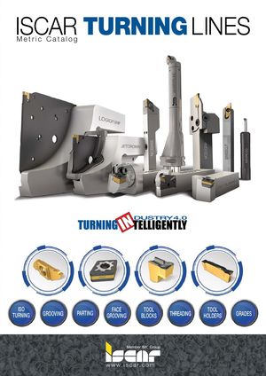 Каталог Iscar токарные державки ISO 2022
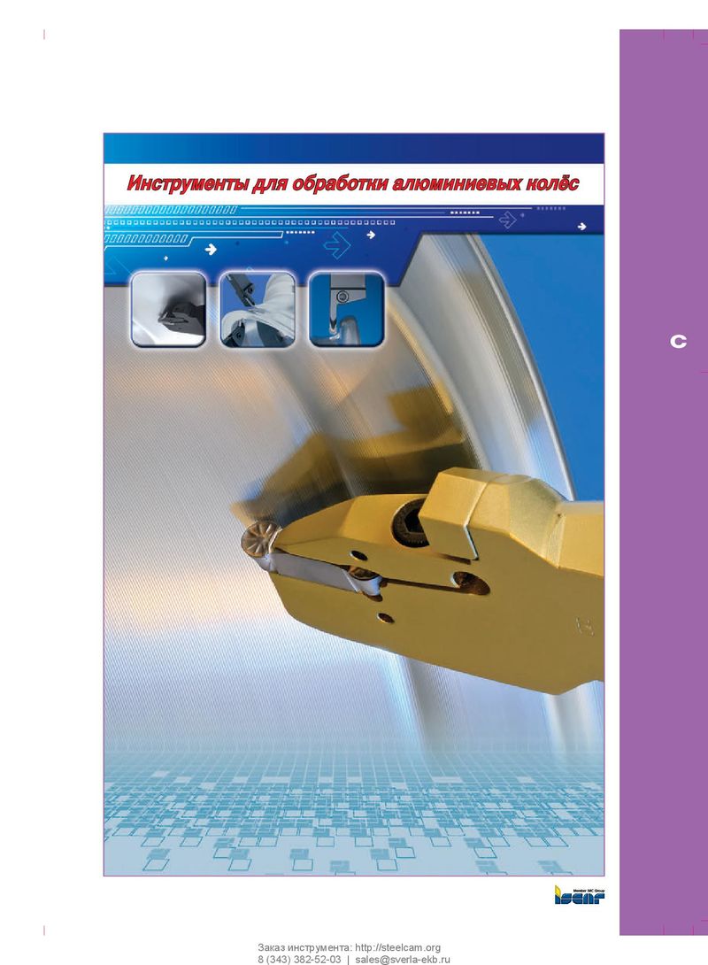 Каталог Iscar инструмент для обработки алюминиевых колёс