Каталог Iscar обработка канавок 2022 - страница 171
Навигация
 Каталог Iscar монолитные концевые фрезы и система multi-master
 Фрезерные инструменты Iscar 2026
 Каталог Iscar сверла ружейные и для глубокого сверления 2022
 Каталог Iscar токарные державки ISO 2022
 Каталог Iscar инструмент для обработки алюминиевых колёс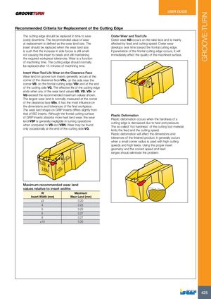
Recommended Criteria for Replacement of the Cutting Edge
| The cutting edge should be replaced in time to save | Crater Wear and Tool Life |
| costly downtime. The recommended value of wear | Crater wear KB occurs on the rake face and is mainly |
| at replacement is defined as the wear land size. The | affected by feed and cutting speed. Crater wear |
| insert should be replaced when the wear land size | develops over time toward the frontal cutting edge. |
| is such that the increase in side forces is still small- | If penetration of the frontal cutting edge occurs, it will |
| not causing the insert to break and still maintaining | immediately affect the quality of the machined surface. |
the required workpiece tolerances. Wear is a function of machining time. The cutting edge should normally be replaced after 15 minutes of machining time. Insert Wear-Tool Life Wear on the Clearance Face
Wear land on groove turn inserts generally occurs at the corner of the clearance face VBN, on the side near the corner VB, on the frontal cutting edge VBF and at the end KB of the cutting side VG. The effective life of the cutting edge ends when any of the wear land values-VB, VB, VBF or VG-exceed the recommended maximum values shown. The largest wear land is normally measured at the corner of the clearance face VBN. It has the most influence on the dimensions and tolerances of the final workpiece. The wear land shape on GRIP inserts differs slightly from that of ISO inserts. Although the frontal cutting surface Plastic Deformation of GRIP inserts absorbs more heat land wear, the wear Plastic deformation occurs when the hardness of a land VBF is generally negligible in turning operations cutting edge is decreased due to heat and pressure.
when compared to VB and VBN. Wear may be found “ ”
The so-called hot hardness of the cutting tool material only occasionally at the end of the cutting side VG. limits the feed and the cutting speed. Plastic deformation will affect the dimensions and
tolerances of the finished product. It generally occurs when a small corner radius is used with high cutting speeds and high feeds. Using the proper insert geometry and the correct speed and feed ranges should eliminate the problem.
VG
VB
F
VB
N VB
Maximum recommended wear land
values relative to insert widths
| W | Maximum |
| Insert Width (mm) | Wear Land (mm) |
| ≤3 | 0.20 |
| 4 | 0.22 |
| 5 | 0.25 |
| 6 | 0.27 |
| 8 | 0.27 |
| ≥10 | 0.30 |