Каталог Iscar обработка канавок 2022 - страница 169
Навигация
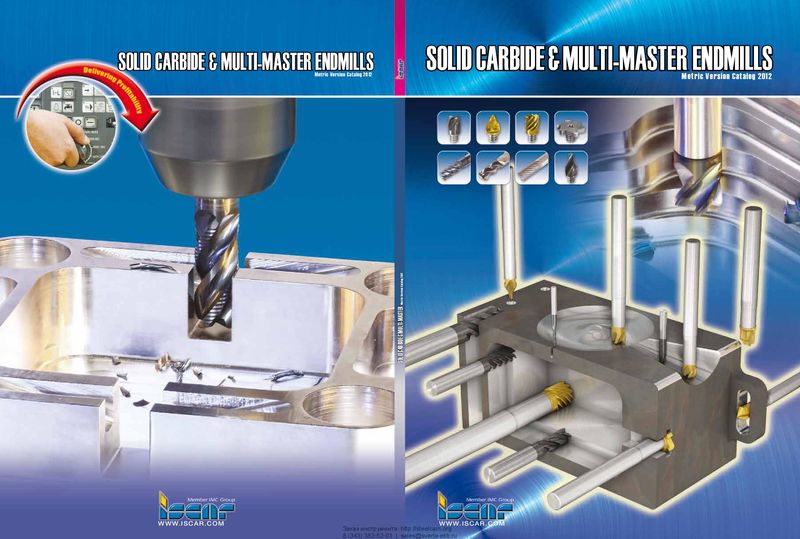 Каталог Iscar монолитные концевые фрезы и система multi-master
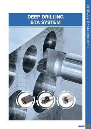 Каталог Iscar сверла ружейные и для глубокого сверления 2022
 Каталог Iscar токарные державки ISO 2022
 Каталог Iscar инструмент для обработки алюминиевых колёс
 Каталог Iscar инструментальная оснастка 2022
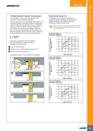
Diameter CompensationDiameter CompensationDiameter Compensation Factor ∆ mmFactor ∆ mmFactor ∆ mm GROOVE-TURNTEXT USER GUIDE Finishing Operation: Diameter Compensation Characteristic Values of ∆ A compensation factor for the final diameter must The diagrams show experimental results for be used in the final machining operation. specific machining conditions. These are sample After the initial grooving to the required final diameter, the values that will vary with different workpiece machining direction is normally changed for longitudinal materials and different holder types. turning. At this point the deflection occurs. If machining Measure the ∆ value for your finishing operation in a short test continues without correction, corner A will penetrate using your selected finishing conditions. Do not run your test the material. This will result in two different diameters: using the final diameter. øD1 from the grooving and øD2 from the turning. The difference between øD1 and øD2 is a value we define as ∆. The compensation factor is ∆/2, as shown below. Insert: GIP 4.00E-0.4 Toolholder: GHDR 25-4 ∆2 = øD1-øD2 2 0.24 ap=4Êmm 0.20 Using the compensation factor will eliminate ap=3Êmm0.16 the small surface step. Follow this simple procedure during machining: 0.12 ap=2Êmm 1 Groove to the final diameter 0.08 2 Pull the tool back, a distance equal to the value of ∆/2 0.04 ap=1Êmm 3 Continue the finish turning operation 0 0.1 0.2 0.3 0.4 0.5 0.6 Characteristic values of ∆ are shown in the diagrams. Feed f (mm/rev) Insert: GIP 3.00E-0.4 Toolholder: GHDR 25-3 ØD2 ØD1ØD1ØD2 0.24 A Δ/2 0.20 ap=3Êmm ap=2Êmm 0.16 0.12 ap=1Êmm 0.08 ap=0.5Êmm 1 ap 0.04 0 0.1 0.2 0.3 0.4 0.5 0.6 Feed f (mm/rev) Insert: GIP 6.00E-0.8 2 Toolholder: GHDR 25-5 Δ/2 0.24 0.20 ap=4Êmm 0.16 0.12 ap=3Êmm 3 0.08 ap=2Êmm 0.04 ap=1Êmm 0 0.1 0.2 0.3 0.4 0.5 0.6 Feed f (mm/rev) 423