Каталог Iscar обработка канавок 2022 - страница 168
Навигация
 Каталог Iscar монолитные концевые фрезы и система multi-master
 Фрезерные инструменты Iscar 2026
 Каталог Iscar сверла ружейные и для глубокого сверления 2022
 Каталог Iscar токарные державки ISO 2022
 Каталог Iscar инструмент для обработки алюминиевых колёс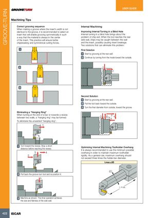
Machining Tips
| Correct grooving sequence | Internal Machining |
| When making a groove where the insert’s width is not | |
| identical to the groove, it is recommended to select an | Improving Internal Turning in a Blind Hole |
| insert that will enable grooving symmetrically in such | Internal turning in a blind hole brings about the |
| a way that the material is always in the center | problem of chip exit. When the tool reaches the rear |
| of the insert. This practice will ensure better | side wall, chips may be caught between the wall |
| chipbreaking and symmetrical cutting forces. | and the insert, possibly causing insert breakage. |
| Two solutions that can eliminate this problem: | |
| 1 First Solution |
1 Start by grooving at the rear wall. 2 Continue by turning from the inside toward the outside.
2 1 2
3
Eliminating a “Hanging Ring” When turning at the end of a bar or towards a recess between two walls, a “hanging ring” may be formed. To eliminate the unwanted “hanging ring”:
1
Second Solution 1 Start by grooving at the rear wall. 2 Pull the tool back toward the outside. 3 Turn the final diameter from outside, toward the groove.
1 2 3 4
5
1 Turn toward the recess. Stop a short distance before reaching the recess.
3 4
2
2 Pull back the groove-turn tool and re-position it. 5
Optimizing Internal Machining Toolholder Overhang It is always recommended to use the minimum possible overhang in order to maintain maximum toolholder rigidity. As a general rule, maximum overhang should not exceed three times the holder-bar diameter. Lmax.≤3D
¯D
LÊmax.
3 Machine as shown. This final operation achieves the size and flatness of the side wall.