Каталог Iscar обработка канавок 2022 - страница 165
Навигация
 Каталог Iscar монолитные концевые фрезы и система multi-master
 Фрезерные инструменты Iscar 2026
 Каталог Iscar сверла ружейные и для глубокого сверления 2022
 Каталог Iscar токарные державки ISO 2022
 Каталог Iscar инструмент для обработки алюминиевых колёс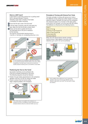
| What is a GRIP Insert? | Principles of Turning with Groove-Turn Tools | |
| A grip insert is a grooving, groove-turn or parting insert | The basic principle in turning with groove-turn tools is | |
| that is clamped between 2 prisms. | the deflection of the cutting tool, which results in a frontal | |
| Clamping a grip insert correctly in the holder | clearance angle αº between the insert and the workpiece. | |
| is necessary for stable machining. | The clearance angle αº is a function of the side cutting | |
| 1 Ensure that the seat is clean of dirt and swarf. | forces and is not constant, as is the case with ISO inserts. | |
| The deflection is influenced by the following factors: | ||
| 2 In the first stage of clamping, ease the insert gently into | ||
| place. Make sure that the prismatic surfaces match. | Feed: f | |
| 3 Always use the wrench supplied with the tool. | Depth of Cut: a | |
| p | ||
| Use reasonable force to the point of resistance | Overhang of Insert Support: T | |
| for final clamping. | Width of Insert Support: A |
The maximum recommended clamping torque is Cutting Speed: V 1.5xd Nm or 15xd Kgf x cm. d=clamping screw dia. in mm. c Workpiece Material
When all of the above factors remain constant 1 during turning, a high degree of accuracy with a tolerance up to ±0.01 mm can be achieved.
f ap α°
2 3 T
It is very important not to overtighten a grip insert, even though you may get the impression that the insert is more secure. When overtightened, the insert doesn’t clamp into its correct and carefully designed clamping points, and therefore, is less stable.
Positioning the Tool on the Turret
Successful machining can be achieved only if the tool is properly positioned on the turret. The following sequence should be followed:
- Position the grip holder perpendicular to the workpiece; A deviation may be 0.10/100 mm along the holder If the conditions are too light (such as in a super finish
- Check to ensure that the frontal cutting operation), there may not be enough deflection and the edge is aligned parallel to the workpiece clearance angle will be very small. This may result in chatter
and vibration.
f 0.10/100 α° 90°±10'
If the cutting edge is not parallel to the workpiece or is positioned as shown, the deflection during machining (in the indicated direction) will be too small and chatter may occur.