Режущие и зажимные инструменты Hoffmann Group 2026 - страница 717
Навигация
 Каталог Hoffmann Group ручной и измерительный инструмент
 Каталог Hoffmann Group режущий и вспомогательный инструмент
 Производственная мебель и системы хранения Hoffmann Group 2026
 Каталог Hoffmann Group токарный инструмент
 Каталог Hoffmann Group запасные части, оснастка и СИЗ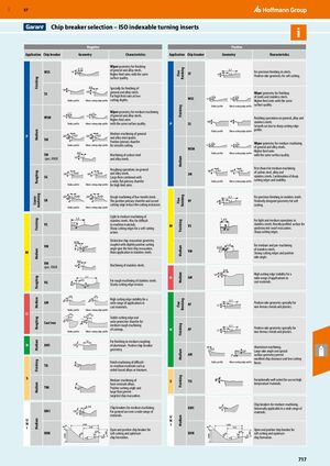
Выбор пластин-держателей – ISO индексируемые вставки для токарной обработки
Отрицательная геометрия
| Применение | Пластина-держатель | Геометрия | Характеристики |
|---|---|---|---|
| Чистовая обработка | WSS | 18°, геометрия радиуса 0,15 | Геометрия вершины для чистовой обработки общих и легированных сталей. Более высокие подачи при той же шероховатости поверхности. |
| SS | 7°, профиль малой режущей кромки | Специально для чистовой обработки общих и легированных сталей. Для высоких подач при малых глубинах резания. | |
| Средняя обработка | WSM | 19°, геометрия радиуса 0,25 / 19°, профиль малой режущей кромки 0,3 | Геометрия вершины для средней обработки общих и легированных сталей. Более высокие подачи при той же качестве поверхности. |
| SM | Геометрия радиуса, профиль малой режущей кромки | Средняя обработка общих и легированных сталей. Положительный первичный фаска для плавного резания. Обработка углеродистой и легированной стали. Операции черновой обработки общих и легированных сталей. Большая канавка в сочетании с широким плоским первичным фаской для высоких подач. | |
| Черновая обработка | SG | Геометрия радиуса, профиль малой режущей кромки | Операции черновой обработки общих и легированных сталей. |
| SR | Геометрия радиуса, профиль малой режущей кромки 1,3 | Черновая обработка низкоуглеродистых сталей. Положительный первичный фаска и изогнутая режущая кромка снижают сопротивление резанию. | |
| Средняя обработка нержавеющей стали | VS | 13°, профиль малой режущей кромки 1,3 | Легкая и средняя обработка нержавеющих сталей. Также для труднообрабатываемых материалов. Острые режущие кромки для мягкого резания. Характерная геометрия эвакуации стружки с немного положительным углом резания обеспечивают лучшую эвакуацию стружки. Основное применение в нержавеющих сталях. |
| VM VM spec. KNUX |
Профиль малой режущей кромки 2,5 / 0,3; 4°, 20° | Средняя обработка нержавеющих сталей. Обработка нержавеющих сталей. | |
| Чугун | GM | Геометрия радиуса, профиль малой режущей кромки 0,13; 20°, 5° | Высокая стабильность режущей кромки для широкого диапазона применений в материалах с матричной структурой. Устойчивая режущая кромка и широкий защитный фаска для средней черновой обработки отливок. |
| Cast iron | Геометрия радиуса, профиль малой режущей кромки | Для чистовой и средней черновой обработки алюминия. Положительная геометрия пластины-держателя. | |
| Алюминий | AM1 | Геометрия радиуса, профиль малой режущей кромки | Чистовая обработка труднообрабатываемых материалов, таких как никелевые сплавы или титан. |
| TIS | Средняя обработка жаропрочных сплавов. | ||
| Универсальная | TIM UM1 XUM |
Положительный угол резания и большая канавка обеспечивают целевую эвакуацию стружки. Пластины-держатели для средней обработки. Для общего использования в широком диапазоне материалов. Открытая и положительная пластина-держатель для мягкого резания и оптимального образования стружки. |
Положительная геометрия
| Применение | Пластина-держатель | Геометрия | Характеристики |
|---|---|---|---|
| Чистовая обработка | SF | 9°, 0,2 | Для прецизионной чистовой обработки сталей. Положительная геометрия переднего угла для мягкого резания. |
| Чистовая обработка | WSS | 20°, 12°, геометрия радиуса / профиль малой режущей кромки 0,12 / 16°, 8° | Геометрия вершины для чистовой обработки сталей и нержавеющих сталей. Более высокие подачи при том же качестве поверхности. |
| P / SS | Профиль малой режущей кромки, геометрия радиуса | Операции чистовой обработки общих, легированных и нержавеющих сталей. Плавное резание благодаря острой режущей кромке. | |
| Средняя обработка | WSM | 18°, 7°, геометрия радиуса / профиль малой режущей кромки 0,2 / 0,2 | Геометрия вершины для средней обработки общих и легированных сталей. Более высокие подачи при том же качестве поверхности. |
| P / SM | Геометрия радиуса, профиль малой режущей кромки | Первый выбор для средней обработки углеродистых сталей, легированных и нержавеющих сталей. Комбинация острых режущих кромок и стабильности. | |
| Чистовая обработка нержавеющей стали | VF | 9°, 0,2 | Для прецизионной чистовой обработки нержавеющих сталей. |
| M / VS | 8°, профиль малой режущей кромки 1,45 | Для легкой и средней обработки нержавеющих сталей. Сильно профилированная поверхность для беспрепятственной эвакуации стружки. Острые режущие кромки. | |
| Средняя обработка нержавеющей стали | M / VM | Профиль малой режущей кромки, 0,35 / 0,1 для 1,8 | Для средней и предварительной обработки нержавеющих сталей. Прочные режущие кромки и положительный передний угол. Высокая стабильность режущей кромки для широкого диапазона применений. |
| Чугун | O / GM | Профиль малой режущей кромки 0,7 | Высокая стабильность режущей кромки для широкого диапазона применений в материалах с матричной структурой. |
| Цветные металлы | N / AF | 15°, 0,2 / 0,7 | Положительная геометрия переднего угла специально для цветных металлов и пластмасс. |
| N / AF | 15°, 0,2 | Положительная геометрия переднего угла специально для цветных металлов и пластмасс. Обработка алюминия. Большой передний угол и специальная геометрия поверхности обеспечивают отличную эвакуацию стружки и низкие силы резания. | |
| Чистовая обработка | N / AM | Профиль малой режущей кромки, геометрия радиуса | Отлично подходит для использования на жаропрочных материалах. Пластины-держатели для средней обработки. Универсально применимо в широком диапазоне материалов. |
| Чистовая обработка | S / TIS | Исключительно хорошо подходит для использования на высокотемпературных материалах. | |
| Универсальная | U / XUM | Открытая и положительная пластина-держатель для мягкого резания и оптимального образования стружки. |