Общий каталог Dijet 2018 - страница 436
Навигация
 Общий каталог Dijet 2012 на русском
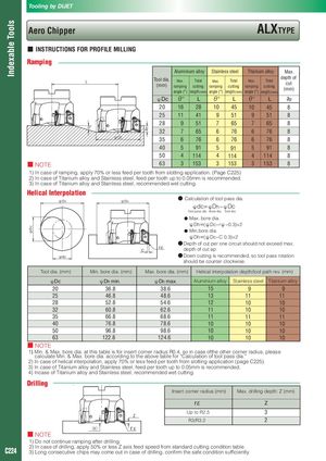
Indexable Tools φD C ap Tooling by DIJET Aero Chipper ALXTYPE ■ INSTRUCTIONS FOR PROFILE MILLING Ramping Aluminium alloy Stainless steel Titanium alloy Max. L Tool dia.(mm) Max. Total Max. Total Max. Totalrampingcuttingrampingcuttingrampingcuttingangle (°)length (mm)angle (°)length (mm)angle (°)length (mm)depth ofcut(mm) ϕDc θ° L θ° L θ° L ap 20 16 28 10 45 10 45 8 25 11 41 9 51 9 51 8 28 9 51 7 65 7 65 8 θ° 32 7 65 6 76 6 76 8 φDC 35 6 76 6 76 6 76 8 40 5 91 5 91 5 91 8 50 4 114 4 114 4 114 8 ■ NOTE 63 3 153 3 153 3 153 8 1) In case of ramping, apply 70% or less feed per tooth from slotting application. (Page C225) 2) In case of Titanium alloy and Stainless steel, feed per tooth up to 0.05mm is recommended. 3) In case of Titanium alloy and Stainless steel, recommended wet cutting. Helical Interpolation φD h φD h ● ● Calculation of tool pass dia. ϕdc=ϕDh−ϕDc Tool pass dia. Bore dia. Tool dia. ● Max. bore dia. ϕDh=(ϕDc−rϕ−0.3)×2 ● Min.bore dia. ϕDh=(ϕDc−C 0.3)×2 ● ● Depth of cut per one circuit should not exceed max. C rε depth of cut ap φdC ● ● Down cutting is recommended, so tool pass rotation should be counter clockwise. Tool dia. (mm) Min. bore dia. (mm) Max. bore dia. (mm) Helical interpolation depth/tool path rev. (mm) ϕDc ϕDh min. ϕDh max. Aluminium alloy Stainless steel Titanium alloy 20 36.8 38.6 15 9 9 25 46.8 48.6 13 11 11 28 52.8 54.6 12 10 10 32 60.8 62.6 11 10 10 35 66.8 68.6 11 11 11 40 76.8 78.6 10 10 10 50 96.8 98.6 10 10 10 63 122.8 124.6 10 10 10 ■ NOTE 1) Min. & Max. bore dia. at this table is for insert corner radius R0.4, so in case ofthe other corner radius, please calculate Min. & Max. bore dia. according to the above table for “Calculation of tool pass dia.“ 2) In case of helical interpolation, apply 70% or less feed per tooth from slotting application (page C225). 3) In case of Titanium alloy and Stainless steel, feed per tooth up to 0.05mm is recommended. 4) Incase of Titanium alloy and Stainless steel, recommended wet cutting. Drilling Insert corner radius (mm) Max. drilling depth: Z (mm) rε Z Up to R2.5 3 Z R3/R3.2 2 (X) rε ■ NOTE TE 1) Do not continue ramping after drilling. C224 2) In case of drilling, apply 50% or less Z axis feed speed from standard cutting condition table.3) Long consecutive chips may come out in case of drilling, confirm the safe condition sufficiently.